Caution – Goulds Pumps 3408 - IOM User Manual
Page 42
38
3408 IOM 03/99
4.
Tap the stuff ing boxes with a soft-headed ham mer
to break the seal be tween the stuff ing box and lower
cas ing half, and lift the ro tat ing el e ment out of the
lower cas ing. Ro tating el e ment may now be moved
to a suit able work ing lo ca tion. (See Fig. 19)
NOTE: A spare rotating element can be
installed at this point.
5.
Re move four cap screws (3-904-9) from each
bear ing hous ing (3-025-3 and -4) and re move the
bear ing hous ings from the shaft (3-007-0).
6.
Bend back lockwasher tab and re move locknut
(3-516-4) and lockwasher (3-517-4) from the
out board end of the shaft and, us ing a puller,
re move the outboard bear ing (3-026-4) from the
shaft. Re move the in board end bear ing (3-026-3)
in the same man ner.
NOTE: Locknut and lockwasher are not used
on inboard end bearing.
▲
!
CAUTION
Do not reuse the ball bearings.
7.
Slide both stuff ing boxes (3-073-9) off of the shaft,
work ing de flec tor rings (3-136-9) off the shaft at
the same time. (See Fig. 20.)
8.
Re move lip seals (3-177-9) from the stuff ing
boxes.
9.
Re move the two gland bolts (1-904-9), gland
halves (1-014-9), pack ing (1-924-9) and, if
sup plied, seal cage (1-013-9) from each stuff ing
box. Re move the O-rings (3-914-1) from the
stuff ing boxes.
10. Re move the two cas ing rings (3-003-9) from the
im pel ler (4-002-0) and re move O-rings (3-914-2)
from each cas ing ring.
NOTE: Each casing ring on 8 x 10-20 and
10 x 12-18 has 2 O-rings. (See Fig. 21B, page 39)
11. Loosen set screw (3-902-3) in shaft nuts (3-015-9)
and then re move shaft nuts us ing pin span ner
wrench. Re move O-rings (3-914-9) from
counterbore in shaft sleeves.
NOTE: Both shaft nuts have right handed
threads.
12. To remove the sleeve, hold the shaft vertically
and tap it on a block of wood. The impeller weight
should force both the impeller and sleeve from the
shaft.
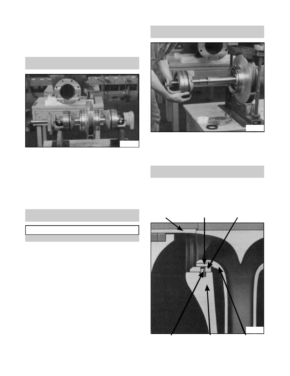
Fig. 20
(3-009-9)
SLEEVE
(0-004-0)
IMPELLER RING
(3-003-9)
CASING RING
LOCKING PIN
(3-943-9)
CASING
(2-001-0)
IMPELLER
(4-002-0)
Fig. 21A
Fig. 19