Warning, Fig. 39, Setting dimensions – Goulds Pumps 3408 - IOM User Manual
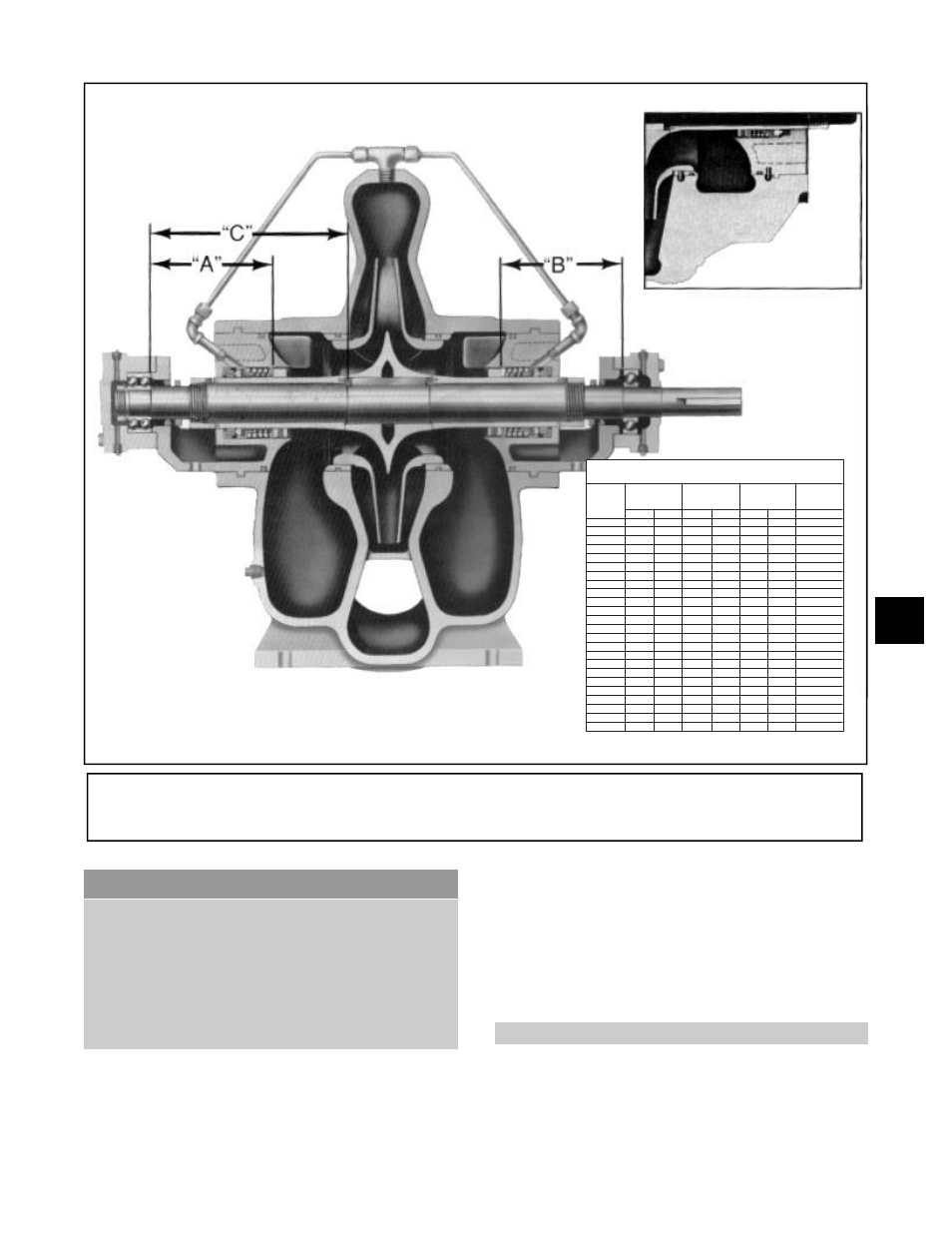
Page 51: Dowel pin location at parting line
▲
!
WARNING
Prior to working on pump the power source
should be disconnected with lockout
provisions so power cannot be re-energized
to the motor. Close isolating suction and
discharge valves. Failure to follow these
instructions could result in property
damage, severe personal injury, or death.
(See explosion view on page 65.)
1.
Drain the pump by opening vent plug (A, Fig. 40)
and remove drain plugs (B and C) on the suction
and discharge nozzles.
3408 IOM 03/99
47
2.
Remove all casing main joint cap screws(2-904-1)
and dowels (2-916-1). Remove external tubing
(0-952-0) if supplied.
3.
Insert a screwdriver or pry bar into the slots
between the upper and lower casing halves, and
separate the halves, lifting off the upper casing
half.
NOTE: Some casings have jacking screws.
4.
Tap the stuffing boxes with a soft-headed hammer
to break the seal between the stuffing box and
lower casing half, and lift the rotating element out
of the lower casing. Rotating element may now be
removed to a suitable location to work on.
(See Fig. 41)
DISMANTLING
(PUMP WITH MECHANICAL SEALS ON SHAFT SLEEVES)
Fig. 39
SETTING DIMENSIONS
PUMP
SIZE
TYPE 1
MECH. SEAL
TYPE 21 MECH.
TYPE 1B
MECH.
IMPELLER
LOCATING
DIMENSIONS
SEAL
(STANDARD)
SEAL
“A”
“B”
“A”
“B”
“A”
“B”
“C”
2 x 3-11
6.62
6.75
6.00
6.12
7.00
7.12
8.755
4 x 6-9
9.312
4 x 6-10
7.56
7.75
6.94
7.12
8.06
8.25
10.625
4 x 6-11
7.56
7.75
6.94
7.12
8.06
8.25
10.625
4 x 6-12
6.62
6.75
6.00
6.12
7.00
7.12
9.755
4 x 6-14
6.62
6.75
6.00
6.12
7.00
7.12
9.755
6 x 6-9
9.312
6 x 8-9
6.62
6.75
6.00
6.12
7.00
7.12
9.755
6 x 8-10
10.625
6 x 8-12
6.62
6.75
6.00
6.12
7.00
7.12
9.755
6 x 8-12M
7.56
7.75
6.94
7.12
8.06
8.25
10.625
6 x 8-13
7.31
7.50
6.69
6.88
7.81
8.00
10.625
6 x 8-17
7.31
7.50
6.69
6.88
7.81
8.00
10.625
6 x 8-18
7.31
7.50
6.69
6.88
7.81
8.00
10.625
8 x 8-12
7.31
7.50
6.69
6.88
7.81
8.00
10.625
8 x 8-17
7.88
8.00
7.06
7.18
8.25
8.36
11.495
8 x 10-12
7.88
8.00
7.06
7.18
8.25
8.36
11.495
8 x 10-17
7.88
8.00
7.06
7.18
8.25
8.36
11.495
8 x 10-20
7.88
8.00
7.06
7.18
8.25
8.36
11.495
10 x 10-12
7.88
8.00
7.06
7.18
8.25
8.36
12.995
10 x 12-12
7.88
8.00
7.06
7.18
8.25
8.36
12.995
10 x 12-14
7.88
8.00
7.06
7.18
8.25
8.36
11.495
10 x 12-17
7.88
8.00
7.06
7.18
8.25
8.36
11.495
10 x 12-18
7.88
8.00
7.06
7.18
8.25
8.36
11.495
6
Dowel Pin Location
at Parting Line