Caution – Goulds Pumps 3408 - IOM User Manual
Page 50
46
3408 IOM 03/99
14. Install lockwasher (3-517-4) and locknut(3-516-4)
on the outboard end of the shaft. Make certain
locknut is secured and then bend over tabs on
lockwasher.
15. Allow the bearing to cool to room temperature. On
grease lubricated bearings only, coat the exposed
sides with two or three ounces of recommended
grease.
16. On grease lubricated bearings, coat the inside of the
bearing housing (3-025-4) with grease and slide into
place over bearing. Attaching the bearing housing to
the stuffing box with four cap screws (3-904-9).
17. Repeat steps 9 through 13, 15 and 16 for the
inboard end.
NOTE: A locknut and lockwasher are not installed
on the inboard end of the shaft.
18. Clean the gasket surfaces of the casing. Apply
Scotch 3M-77 spray adhesive or equivalent to the
lower half of the casing.
19. Within one minute of spraying, set the untrimmed
gaskets (2-123-5 and -6) in place on the lower half
casing, align the holes in the gaskets with the holes in
the casing and press the gaskets firmly against the
lower half casing face in the area coated by the
adhesive.
20. Trim the gaskets flush with the lower casing bores, if
this has not been done as yet.
▲
!
CAUTION
Machined casing bores must remain sharp at the
casing parting line. Gaskets must be flush with
bore in order to contact O-rings. Leakage can
result around stuff box O-ring if this step is not
properly followed.
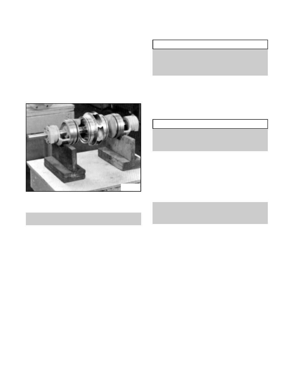
21. Set the rotating element (Fig. 38) in the pump
casing (2-001-0), assuring correct rotation. Locate
both stuffing box tongues in their respective
casing grooves. Locate pins (3-943-9) in the
stuffing box and the casing wear rings in their
respective slots at the casing parting surface.
Correct any O-ring bulging.
▲
!
CAUTION
Do not cut or damage O-rings when lowering the
rotating element into position. When all four
anti-rotation pins (3-943-9) are correctly located,
there will be some casing ring looseness.
22. Lower the upper half casing (2-001-0) into place
using the tapered dowel pins (2-916-1) and install
casing main joint bolts (2-904-1). The casing joint
bolts should be tightened to the following torques:
140 ft-lb minimum for 5/8"-11 hex head cap screws
(Grade 5); 350 ft-lb minimum for 7/8"-9 Ferry Cap
Countr-bor screws (Grade 8). bolt torquing pattern is
shown in Fig. 58, page 55.
NOTE: Torquing bolts to proper values in
proper sequence is essential in obtaining
proper gasket compression so no leakage can
occur at main joint.
23. Rotate the shaft by hand to assure that it turns
smoothly and is free from rubbing or binding.
24. Install seal water piping (0-952-0).
Fig. 38