Location, Foundation, Setting the baseplate – Goulds Pumps 3408 - IOM User Manual
Page 14
14
3408 IOM 03/99
LOCATION
The pump should be installed as near the suction
supply as possible, with the shortest and most direct
suction pipe practical. The total dynamic suction lift
(static lift plus friction losses in suction line) should not
exceed the limits for which the pump was sold.
The pump must be primed before starting. Whenever
possible, the pump should be located below the fluid
level to facilitate priming and assure a steady flow of
liquid. This condition provides a positive suction head
on the pump. It is also possible to prime the pump by
pressurizing the suction vessel.
When installing the pump, consider its location in
relation to the system to assure that sufficient Net
Positive Suction Head (NPSHA) is available at the
pump inlet connection. Available NPSH must always
equal or exceed the required NPSH (NPSHR) of the
pump.
The pump should be installed with sufficient accessibility
for inspection and maintenance. A clear space with ample
head room should be allowed for the use of an overhead
crane or hoist sufficiently strong to lift the unit.
NOTE: Allow sufficient space to be able to
dismantle pump without disturbing the pump inlet
and discharge piping.
Select a dry place above the floor level wherever
possible. Take care to prevent pump from freezing during
cold weather when not in operation. Should the possibility
of freezing exist during a shut-down period, the pump
should be completely drained, and all passages and
pockets where liquid might collect should be blown out
with compressed air.
Make sure there is a suitable power source available for
the pump driver. If motor driven, the electrical
characteristics of the power source should be identical to
those shown on motor data plate.
FOUNDATION
The foundation must be substantial enough to absorb
vibration. (Hydraulic Institute Standards recommends
the foundation weigh at least five (5) times the weight of
the pump unit.) It must form a permanent and rigid
support for the baseplate. This is important in
maintaining the alignment of a flexibly coupled unit.
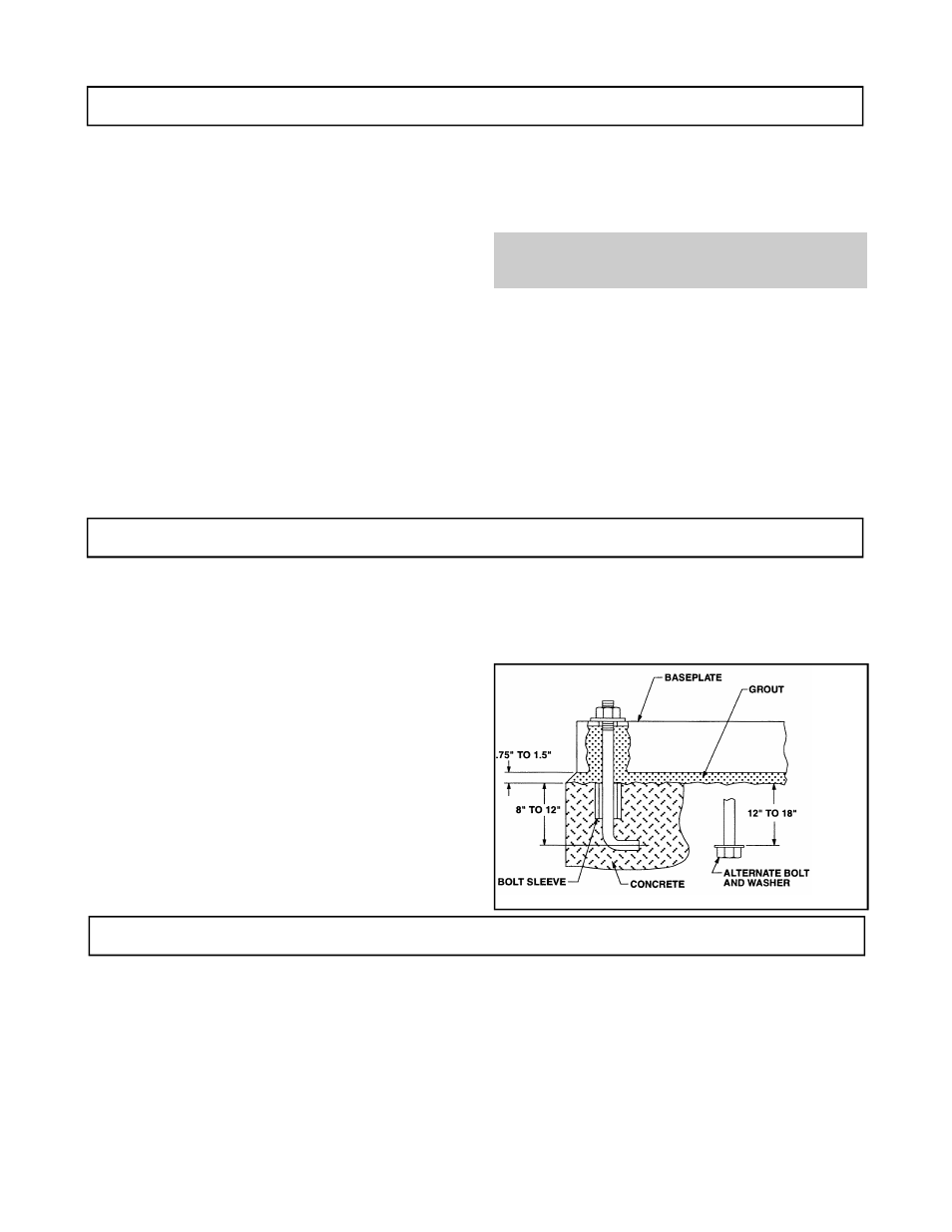
Foundation bolts of the proper size should be embedded
in the concrete to a depth of eight (8) to twelve (12)
inches and locked with either a hook around a
reinforcing bar or alternatively, a nut and washer at the
bottom. The bolts should have a sleeve around them at
least six (6) times the bolt diameter in length and at least
two (2) bolt sizes larger in I.D. If a nut and washer are
used for locking, the washer should have an O.D. two
(2) sizes larger than the sleeve. Foundation bolts should
be sized .125" less than the anchor bolt holes in the
base.
The foundation should be poured to within .75" - 1.5"
of the finished height. (See Fig. 8) Freshly poured
foundations should be allowed to cure for several
days before the unit is set in place and grouted.
SETTING THE BASEPLATE
Pump units are checked at the factory for align ability to
required tolerances.
Due to flexibility of an ungrouted base and handling in
shipment, it should not be assumed that the unit is in
alignment when it is placed on the rough foundation.
If these directions are followed, the required alignment
should be readily achieved.
Initial or rough alignment must be done prior to grouting of
baseplate. Rough alignment is designated as .020" TIR
(Total Indicator Reading) parallel alignment and .009" TIR
per inch of radius angular alignment (See ALIGNMENT
PROCEDURE). Use blocks at anchor bolts and midway
between to position bottom of base at finished height
(See Fig. 9) with foundation bolts extending through holes
in the baseplate. Metal wedges with a small taper may be
used in lieu of blocks and shims.
Fig. 8