Goulds Pumps 3408 - IOM User Manual
Page 45
3408 IOM 03/99
41
▲
!
CAUTION
Machined casing bores must remain sharp at
the casing parting line. Gaskets must be flush
with bore in order to contact O-rings. Leakage
can result around stuff box O-ring if this step
is not properly followed.
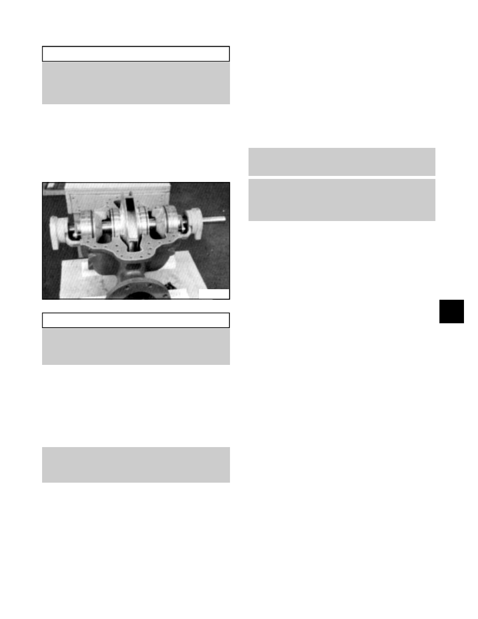
22. Set the rotating element in the pump casing
(2-001-0), assuring correct rotation. Locate both
stuffing box tongues in their respective casing
grooves. Locate pins (3-943-9) in the stuffing box
and the casing wear rings in their respective slots
at the casing parting surface. Correct any O-ring
bulging. (See Fig. 26)
▲
!
CAUTION
Do not cut or damage O-rings when lowering
the rotating element into position. When all four
anti-rotation pins (3-943-9) are correctly located,
there will be some casing ring looseness.
23. Lower the upper half casing (2-001-0) into place
using the tapered dowel pins (2-916-1) and install
casing main joint bolts (2-904-1). The casing joint
bolts should be tightened to the following torques:
140 ft-lb minimum for 5/8"-11 hex head cap
screws (Grade 5); 350 ft-lb minimum for 7/8"-9
Ferry Cap Countr-bor screws (Grade 8). Bolt
torquing pattern is shown in Fig. 58, page 55.
NOTE: Torquing bolts to proper values in
proper sequence is essential in obtaining
proper gasket compression so no leakage
can occur at main joint.
24. Rotate the shaft by hand to assure that it turns
smoothly and is free from rubbing or binding.
25. Install seal water piping (0-952-0), if supplied.
PACKING (NON-ASBESTOS)
26. Install 12 full rings of packing (6 per stuffing box)
so that the ends butt, leaving no gap between the
packing and the stuffing box. (Refer to the table in
Fig. 17 for packing size.) Tamp the packing fully
to the bottom of the stuffing box. Stagger the
joints of each packing ring at least 90 degrees.
For 3 adjacent rings, use the 4, 8 and 12 o’clock
positions.
NOTE: The last ring in each box may not be
required until after the pump has operated for
a period of time.
NOTE: When supplied, the seal cage will
replace the third packing ring from the bottom,
requiring only 5 rings of packing per stuffing
box. The seal cage must aligned with the seal
water inlet when the packing is compressed.
Assemble the glands (1-014-9), washers
(0-909-0), and bolts (1-904-9) square with the
stuffing box and pull up tight. Then loosen the
gland bolts (1-904-9) to permit the packing to
expand. Then retighten finger tight. Final
adjustment of the gland bolts must be done with
the pump running. Allow 30 minutes between
adjustments. A good adjustment should allow
approximately one (1) drip per second from each
gland.
OPTIONAL METHOD FOR INSTALLING PACKING
(AFTER PUMP DISASSEMBLY)
Place stuffing box (3-073-9) on a table or workbench
with the stuffing box opening up. Assemble the packing
per step 26 with the shaft sleeve placed in the stuffing
box. After completing step 26, remove shaft sleeve and
continue to assemble pump per step 4.
The entire assembly may then be placed into position
over the sleeve in step 11.
Fig. 26
6