Dmx pathfinder lr dmx pathfinder operations, Dmx distribution system - block diagram – Pathway LR Manual User Manual
Page 55
DMXPathfinder LR
DMXPathfinder Operations
54
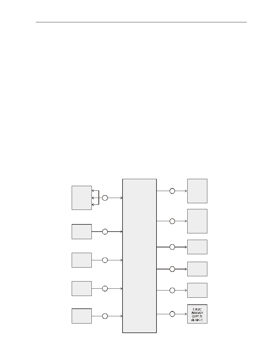
To accommodate the above requirements, a typical DMX Distribution
System consists of the following major components:
.5
Remote DMX input stations; in the control room, on the stage, and
in other locations, for connection of control consoles or other DMX source units.
.6
Remote DMX output stations, located on FOH lighting positions,
onstage lighting pipes, and spaced evenly around the stage or studio, for
connection of DMX-controlled (receiving) equipment.
.7
One or more distribution rack(s), which provides the means of
patching inputs to outputs, and incorporates all necessary electronics and cable
terminations.
.8
A personal computer with patch editing software, which includes a
data link to the distribution rack(s) for transferring patch file and diagnostic
information to and from the rack.
This is block diagram of a typical DMX Distribution System (example is
CBC Toronto Studio 42).
SOUTH
CONTROL
ROOM
CROSSPOINT
ROUTER
DISTRIBUTION
RACK
16 INPUTS
172 OUTPUTS
NORTH
STUDIO
WALL
SOUTH
STUDIO
WALL
DIMMER
ROOM
PERSONAL
COMPUTER
CONTROL RM
STUDIO WALLS
DMX INPUT
STATIONS
DMX DISTRIBUTION SYSTEM - BLOCK DIAGRAM
DMX OUTPUT
STATIONS
DIMMER
RACKS
DMX
NON-DIMS
BATTEN
DMX
STATIONS
PLAK
DMX
STATIONS
WALL
DMX
STATIONS
6
3
3
3
1
2
2
104
144
16
8