Vaddio WallVIEW HD-19 DVI/HDMI User Manual
Page 9
WallVIEW HD-19 DVI/HDMI
WallVIEW HD-19 DVI/HDMI Manual 342-0267 Rev. C
Page 9 of 24
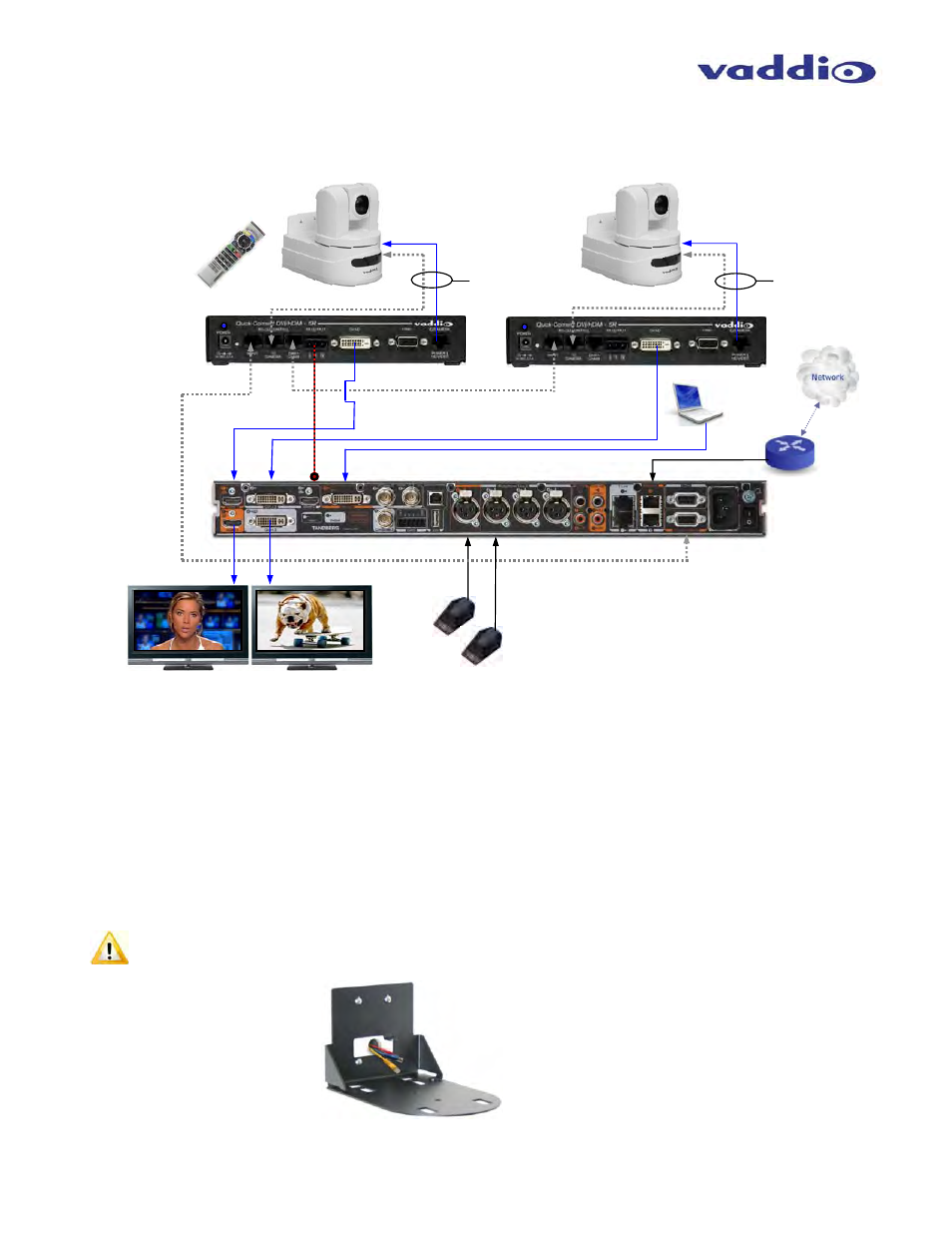
System Connectivity Example 2: System connectivity of two (2) Vaddio HD-19 cameras and two (2) Quick-
Connect DVI/HDMI SR Interfaces configured with single control port codec and Daisy Chain Control Emulation
(DCCE).
Mounting and Installation Instructions for the CONCEAL Wall Mounting System:
Step 1: Determine Camera Mount Location
Note: When locating the camera, consider viewing angles, lighting conditions, possible line of site obstructions
and check for in-wall obstructions where the camera is to be mounted. Pick a mounting location to optimize the
performance of the camera.
The 2 (two) Cat-5e cables should feed-through a 1” (25.4mm) opening (circular or square shape) centered in the
rectangular slot located on the rear flange of the CONCEAL Wall Mount Bracket (see Fig. 1).
Note: Do not cut out the entire rectangular slot opening in the wall! This will not allow the two (2) lower
wall anchors to correctly fasten the Conceal Wall Mount to the wall.
If the bracket is to be mounted on a 2-gang wall box, use the screws supplied with the wall box cover plate to
attach the CONCEAL Wall Mount Bracket.
WallVIEW DVI/HDMI HD-19
HD Camera Systems
DVI to HDMI
Cable
IR
Daisy Chain Link between
Quick-Connect Interfaces
DVI Cable
Computer
with DVI
Output
C60 Codec
Microphones
ETHERNET
DVI Cable
Single RS-232 Port Codec with
Daisy Chain Camera Control
Codec IR Remote:
Forwarded through
Main Camera for
Codec Control
RS-232
RS-232
Two (2) - Cat-5e
Cables - up to
100’ (30.48m)
Power to Camera
HD Video from
Camera - Cat-5e
Power to Camera
HD Video from
Camera - Cat-5e
RS-232 & IR Return Cat-5e
Two (2) - Cat-5e
Cables - up to 100’
(30.48m)
RS-232 & IR Return Cat-5e
HD Video Monitors
(Simulated Video Feeds)
Monitor 1
Monitor 2
DVI-D
HDMI
Quick-Connect
DVI/HDMI SR
Interfaces
Fig. 1: CONCEAL Wall Mount Bracket:
Cabled and Attached to Wall