Vaddio WallVIEW HD-19 DVI/HDMI User Manual
Page 11
WallVIEW HD-19 DVI/HDMI
WallVIEW HD-19 DVI/HDMI Manual 342-0267 Rev. C
Page 11 of 24
Step 5: CONNECT POWER AND TEST:
Connect the 24VDC, 2A power supply to the Quick-Connect and plug it into the wall once all the connections
have been checked. The camera will “HOME” to a centered position. To ensure proper continuity of control
and operation of the cameras, the RS-232 controller (control system, codec or joystick) should be powered ON
after all of the cameras.
Note: Plugging the EZCAMERA POWER & HD VIDEO Cat-5e cable into the wrong
RJ-45 may cause damage to the camera system and void the warranty.
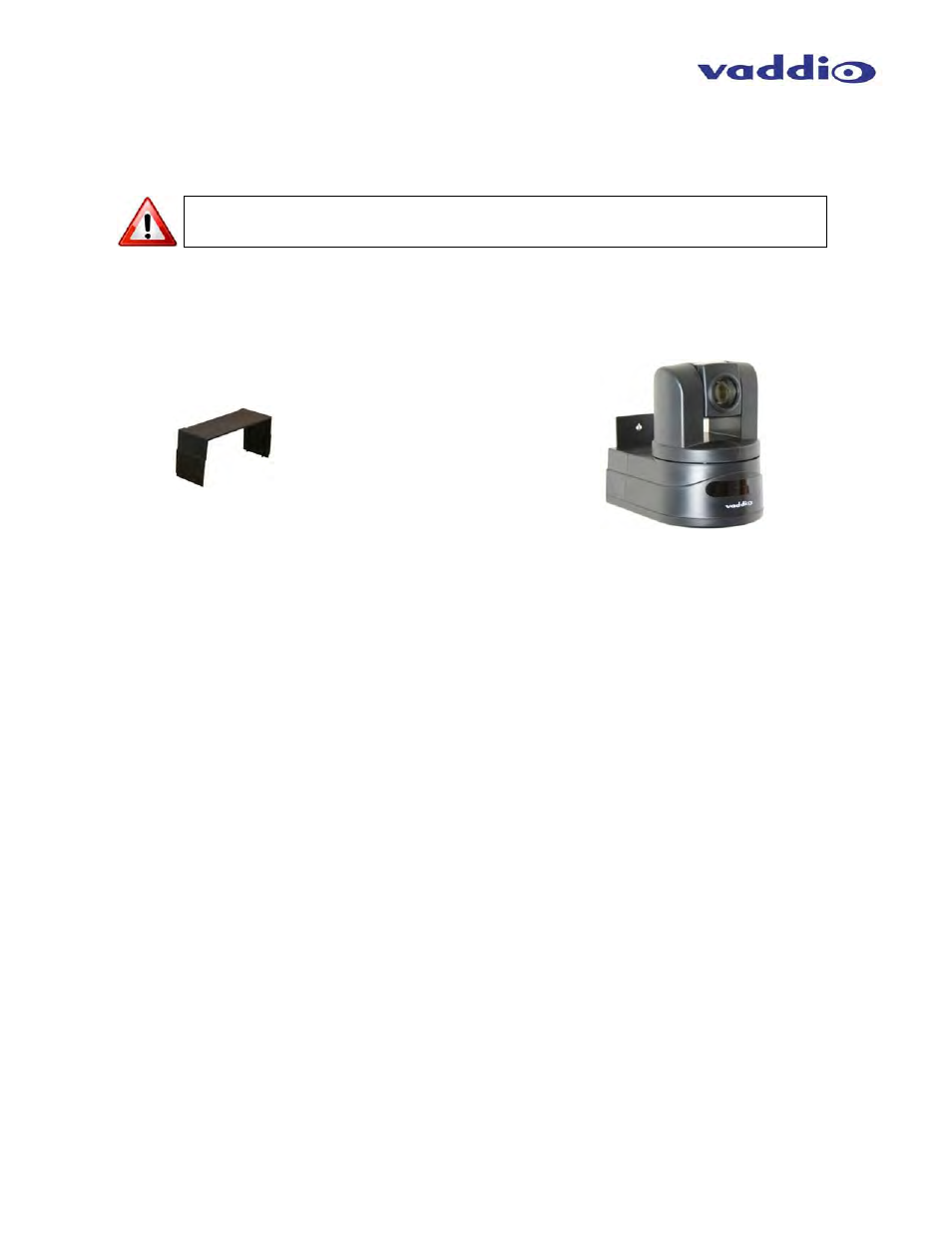
Step 6: INSTALL THE CONCEAL REAR CAMERA COVER:
After successful testing of the camera, install the Conceal Rear Camera Cover on the CONCEAL Mounting
Bracket with the supplied screw (see Fig. 5 and 6).
RS-232 Cabling
For RS-232, use a standard Cat-5e cable (568B termination for RJ-45 connectors) from the RS-232 port on the
back of a Vaddio ProductionVIEW camera controller or switcher. If the camera will be connected to a third-party
control system (such as AMX® or Crestron®), a DB-9 to RJ-45 adapter cable is supplied with the camera for RS-
232
.
Videoconference Codecs and RS-232
Depending on the codec that is used, and which RS-232 port is used with a codec, special DB-9 to RJ-45
adapters may sometimes be required. Refer to Vaddio’s price list or website for Tech Notes on the HD-19 page
on specific diagrams for wiring the camera to videoconference codecs.
Remember to always power up the cameras before booting up the codec.
Step 7: Connect the HD Video Outputs (DVI or HDMI with adapter cable - or - analog HD YPbPr video) into a
display device or video console. Please make sure that the video console or the display device is set up to
receive the HD camera resolution that was chosen with the rotary switch on page 6. Most monitors are
automatic, however all consoles will need set-up prior to termination.
Step 8: Connect the Vaddio 24 VDC, 2.0A power supply to the POWER Connector on the Quick-Connect and
plug the power adapter into an AC outlet. Power will travel down the Power/Video Cat-5e cable to the camera.
The camera will “Home” to a centered position, return HSDS video back to the Quick-Connect and is ready for
control from the IR remote or RS-232 camera controller. Boot Order: Always turn the cameras on first, then
the controller or codec.
Fig. 5: CONCEAL Rear Camera Cover
Fig. 6: Completed CONCEAL Wall
Mount Camera Bracket Installation