Vaddio WallVIEW HD-19 DVI/HDMI User Manual
Page 12
WallVIEW HD-19 DVI/HDMI
WallVIEW HD-19 DVI/HDMI Manual 342-0267 Rev. C
Page 12 of 24
Daisy Chain Configurations/Installation Instructions: In some cases, daisy chain control situations just can’t
be avoided. Because of this, Vaddio added “Daisy Chain Control Emulation” or DCCE™ to the Quick-Connect
DVI/HDMI - SR Interface in order to use the HD-19 camera in these situations. See Connectivity Example 2
(previous page) where the codec requires daisy chain control wiring.
1) For daisy chain control, first complete steps above, since all the cabling between the camera and the Quick-
Connect DVI/HDMI Interface is the same.
2) Instead of running a cable from the 1
st
camera to the 2
nd
camera, run a Cat-5e patch cable from the 1
st
Quick-
Connect DVI/HDMI Interface’s RS-232 CONTROL DAISY CHAIN RJ-45 jack, to the 2
nd
Quick-Connect DVI-
HDMI SR Interface’s RS-232 CONTROL INPUT RJ-45 jack.
3) Within the modified VISCA® protocol that the codec and the HD-19 use, the 1
st
in the chain will set up as
Camera #1, the second will set up as Camera #2 in the chain, allowing the codec IR remote to select which
camera it will switch to and which to control.
4) In the case of TANDBERG codecs, use the IR Modulated output of the Quick-Connect and a Xantech IR
emitter (282D or 283D) and attach the emitter to the front panel of the codec (in front of the IR receiver).
5) Polycom codecs with IR receivers can connect the IR feed-through the same way as the TANDBERG, but do
not use daisy chain control. Several Polycom codecs can also be connected directly with the non-modulated
signal to the codec’s IR signal input port.
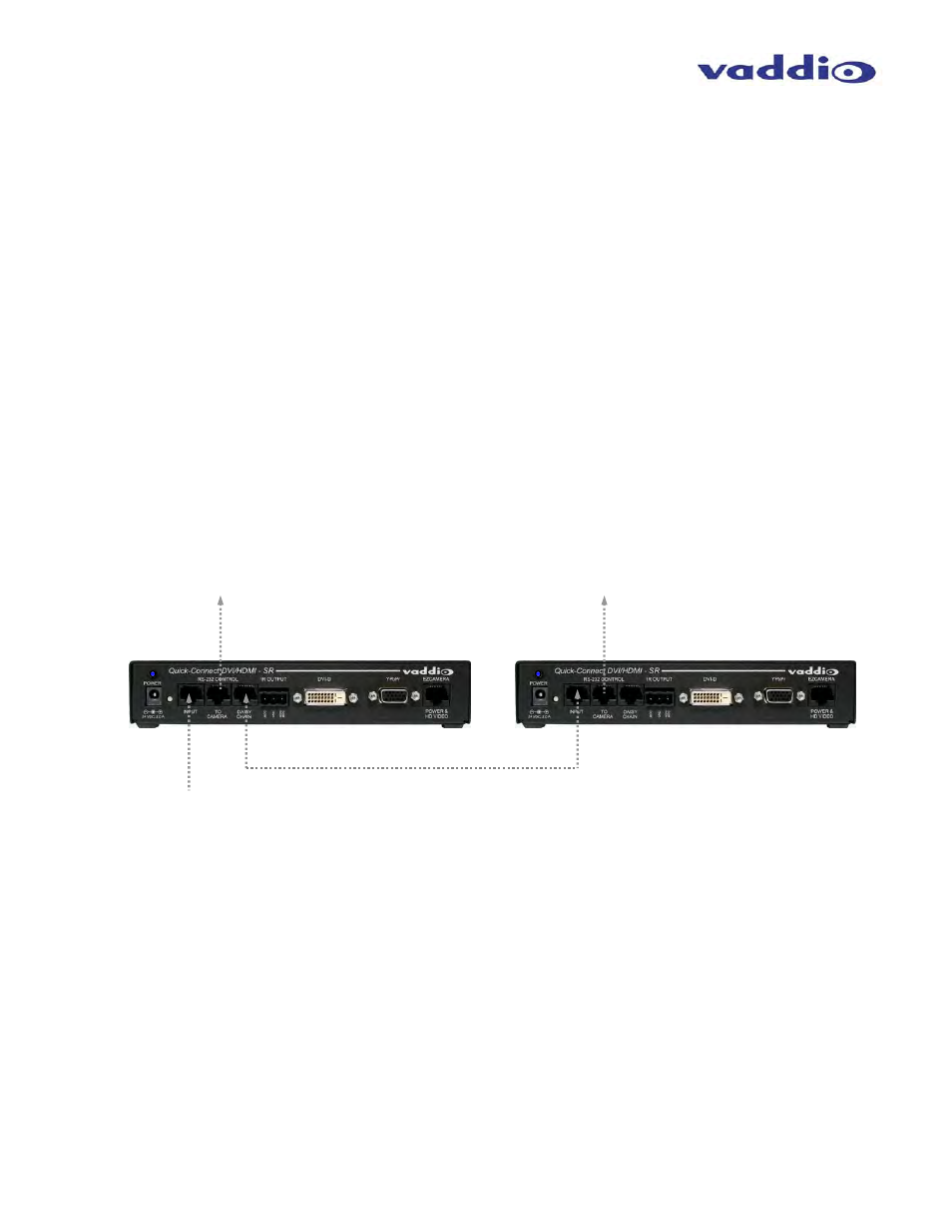
Basic Daisy Chain Connectivity:
RS-232 from Codec
Single Control Port
Daisy Chain Port Out
RS-232
To Camera
#2
RS-232
To Camera
#1
RS-232 Control IN
RS-232