Vaddio WallVIEW HD-19 DVI/HDMI User Manual
Page 10
WallVIEW HD-19 DVI/HDMI
WallVIEW HD-19 DVI/HDMI Manual 342-0267 Rev. C
Page 10 of 24
If mounting to drywall with wall anchors, use the four (4) quality wall anchors/screws provided (see Fig. 1). The
mounting holes are slotted and are 90° opposing to provide easy leveling. Level the mount and tighten the
mounting screws.
Step 2: System Connectivity:
1) Use the accompanying HD-19 manual to set the switch settings for HD video out resolution, IR frequency and
output, baud rate, SD video format and shape, image orientation etc…
2) See “Connectivity Example 1” on page 6. This is the basic two (2) Cat-5e cable system where Power is sent
to the camera and HD Video is returned from the camera on one Cat-5e (blue line) and RS-232 control
communication and IR feed-through is returned from the camera (dashed grey line):
a. Connect the first Cat-5e cable from the EZCAMERA POWER & HD VIDEO RJ-45 jack on the Quick-
Connect to the EZ POWER VIDEO RJ-45 jack on the back of the camera
b. Connect
the
2
nd
Cat-5e cable from the RS-232 CONTROL “TO CAMERA” port to the RS-232 IN/IR
OUT jack on the back of the HD-19 camera. Connect the control source (i.e. Vaddio’s Precision
Camera Controller, ProductionVIEW HD, ControlVIEW™ XHD, AutoPresenter™ etc…) to the RS-232
CONTROL INPUT.
c. Connect the DVI-D output to a DVI-D video device (or HDMI with a DVI-D to HDMI adapter cable -
sold separately) and/or connect the YPbPr output to a different video destination device. Both the
DVI-D and the YPbPr are live images at the same resolution which is set at the camera. The only
difference is that the DVI-D signal is digital and the YPbPr is analog. Both are capable of
1080p/60Hz.
d. Check all Cat-5e cables for proper connection and check the cables for continuity in advance of final
connection. Please do not use the “feed-thru” or “EZ” type RJ-45 connectors for professional
installations (see page 3 for Important Safeguards).
Note: Plugging the EZCAMERA POWER & HD VIDEO Cat-5e cable into the wrong
RJ-45 may cause damage to the camera system and void the warranty.
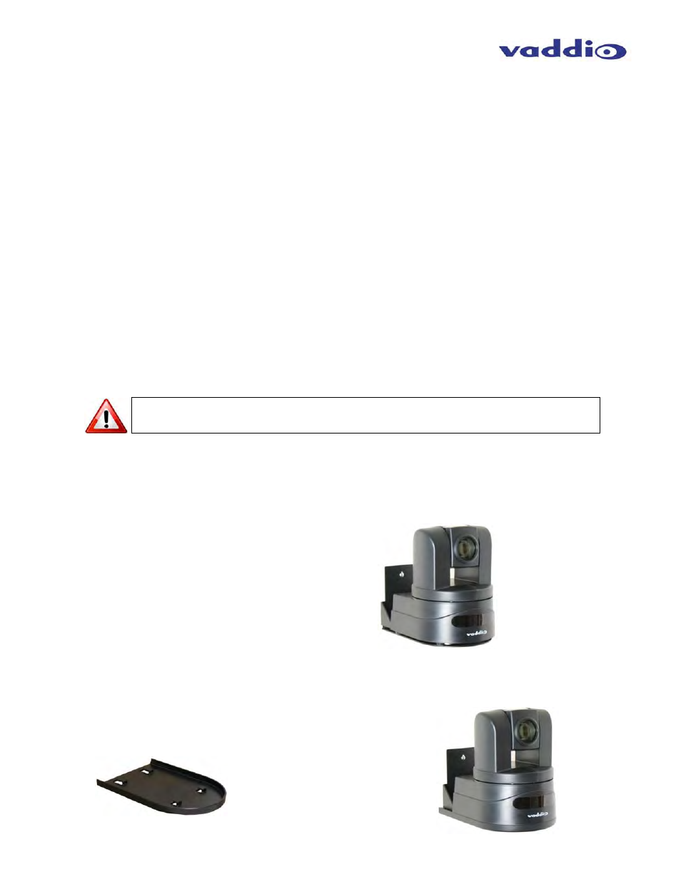
Step 3: SECURE THE CAMERA TO THE CONCEAL WALL MOUNT BRACKET:
After all cables are attached to the camera, place the camera onto the camera mount and insert the two-(1/4”-20)
screws into the camera through the two-screw holes in the bottom of the mount. Note: Be sure to align each
side of the camera evenly to all sides of the CONCEAL Wall Mount Bracket before final tightening of the
mounting screws (see Fig. 2).
Step 4: INSTALL THE CONCEAL LOWER COVER PLATE:
Attach lower CONCEAL Lower Cover Plate (see Fig. 3). Slide lower cover plate from front of the mounting
bracket toward the rear of the bracket. The two-rear locking tabs will need to be guided into position first and will
lock in place as the lower cover plate is pushed toward the rear of the mounting bracket and the front tabs are
inserted (see Fig. 4).
Fig. 2: Vaddio HD-19 Camera aligned
and attached to the CONCEAL Wall
Mount Bracket
Fig. 3: CONCEAL Lower Cover Plate
with Locking Tabs
Fig. 4: CONCEAL Lower
Cover Plate locked in place