Installation, Wiring diagrams – COOK SQN User Manual
Page 2
2
4 5 6
1
7
2
8
3
9
L1 L2 L3
4 5 6
7 8 9
1 2
3
L1 L2 L3
Low Voltage
208/230 Volts
High Voltage
460 Volts
3 Phase, 9 Lead Motor
Y-Connection
7
1
6
7 8 9
4 5 6
1 2
3
Low Voltage
208/230 Volts
High Voltage
460 Volts
8
2
4
9
3
5
L1
L3
L2
L1
L3
L2
3 Phase, 9 Lead Motor
Delta-Connection
Motor
1
2
3
4
5
6
Together
High Speed
Line
L1
L2
L3
1
2
3
4
5
6
Open
Low Speed
Line
L1
L2
L3
Motor
Fan
Motor
Damper
Motor*
Second
Damper
Motor
Transformer**
Transformer**
L3
L2
L1
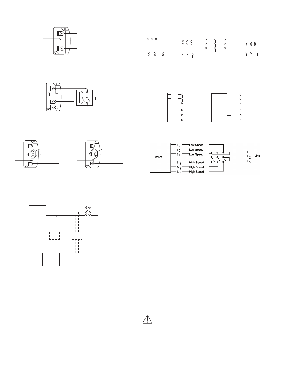
Wiring Diagrams
Wiring Diagrams
When ground is required, attach to ground A or B with no. 6 thread forming
screw. To reverse, interchange T-1 and T-4.
Single Speed, Single Phase Motor
To reverse, interchange any 2 line leads.
When ground required, attach to ground A or B with No. 6 thread forming
screw. To reverse, interchange T-1 and T-4 leads.
2 Speed, 2 Winding, Single Phase Motor
2 Speed, 1 Winding, 3 Phase Motor
To reverse, interchange any 2 line leads. Motors require magnetic control.
Single Speed, Single Phase, Dual Voltage
2 Speed, 2 Winding, 3 Phase
When ground required, attach to ground A or B with No. 6 thread forming
screw. To reverse, interchange T-5 and J-10 leads.
To reverse: High Speed-interchange leads T
11
and T
12
.
Low Speed-interchange leads T
1
and T
2
. Both Speeds-interchange any 2
line leads.
Typical Damper Motor Schematic
For 3 phase, damper motor voltage should be the same between L
1
and
L
2
. For single phase application, disregard L
3
. *Damper motors may be
available in 115, 230 and 460 volt models. The damper motor nameplate
voltage should be verified prior to connection. **A transformer may be pro-
vided in some installations to correct the damper motor voltage to the
specified voltage.
Installation
Motor Installation
To prevent damage to the fan during shipping, motors 5 HP
and larger, and extremely heavy motors (cast iron or
severe duty) are shipped loose and must be field mounted.
Wiring Installation
All wiring should be in accordance with local ordinances
and the National Electrical Code, NFPA 70. Ensure the
power supply (voltage, frequency, and current carrying
capacity of wires) is in accordance with the motor name-
plate. Refer to the Wiring Diagrams.
Direct drive - Wire the electrical box on the blower hous-
ing.
Leave enough slack in the wiring to allow for motor
movement when adjusting belt tension. Some fractional
motors have to be removed in order to make the connec-
tion with the terminal box at the end of the motor. To
remove motor, remove bolts securing motor base to power
assembly. Do not remove motor mounting bolts.
Follow the wiring diagram in the disconnect
switch and the wiring diagram provided with
the motor. Correctly label the circuit on the
main power box and always identify a closed
switch to promote safety (i.e., red tape over a
closed switch).
Ground A
Ground B
T-1
T-4
Low Speed
High Speed
L1
L2
Line
Ground B
J-10
T-5
Ground A
Link A
Link B
Low Voltage
Line
L 2
L 1
Ground A
Link A & B
L1
L 2
Line
Ground B
T-5
J-10
T-1
T-4
Ground B
L2
L1
Ground A
Line