Wiring, Final steps, Operation – COOK Propeller Inline User Manual
Page 3: Inspection, Wiring installation, Final installation steps, Start up
3
Ceiling Mounted Units
a. Mount the fan to its support structure.
b. When all the installation supports have been removed
and the fan is supported only by the permanent struc-
ture, attach the duct work.
c. Drill holes through the flanges to match the duct, then
bolt the duct and flanges together.
Wiring Installation
All wiring should be in accordance with local ordinances
and the National Electrical Code, NFPA 70. Ensure the
power supply (voltage, frequency, and current carrying
capacity of wires) is in accordance with the motor name-
plate. Refer to the Wiring Diagrams, next page.
Leave enough slack in the wiring to allow for motor
movement when adjusting belt tension. Some fractional
motors have to be removed in order to make the connec-
tion with the terminal box at the end of the motor.
Follow the wiring diagram in the disconnect
switch and the wiring diagram provided with the
motor. Correctly label the circuit on the main
power box and always identify a closed switch
to promote safety (i.e., red tape over a closed
switch).
Belt Drive Fans
a. Run wire to the fan. Restrain wire to the housing or
motor plate to prevent it from being pulled into the
shaft.
b. Pull the wire into the motor. For final connections, fol-
low the wiring diagram provided on the motor.
Direct Drive Fans
a. Drill a hole through the fan housing at a convenient
location and pull the wire through it or pull the wire
through the intake duct.
b. Pull the wire into the motor wiring box. Restrain the
wire to prevent it from being pulled into the shaft.
c. For final connections, follow the wiring diagram pro-
vided on the motor.
Final Installation Steps
a. Inspect fasteners and setscrews, particularly fan
mounting and bearing fasteners, and tighten accord-
ing to the recommended torque shown in the table,
Recommended Torque for Setscrews/Bolts.
b. Inspect for correct voltage with voltmeter.
c. Ensure all accessories are installed.
d. Test the fan to be sure the rotation is the same as indi-
cated by the arrow marked Rotation.
NOTICE! Do not allow the fan to run in the wrong
direction. This will overheat the motor and cause seri-
ous damage. For 3-phase motors, if the fan is running
in the wrong direction, check the control switch. It is
possible to interchange two leads at this location so
that the fan is operating in the correct direction.
Operation
Pre-Start Checks
a. Lock out all the primary and secondary power
sources.
b. Inspect fasteners and setscrews, particularly those
used for mounting the unit, and tighten if necessary.
c. Inspect belt tension and pulley alignment. (Remem-
ber, if belt tension is correct, a loud squeal occurs as
the fan increases to full power.)
d. Inspect motor wiring.
e. Ensure the belt touches only the pulleys.
f. Rotate the prop to ensure it does not rub against the
venturi.
g. Ensure fan and ductwork are clean and free of debris.
h. Test the fan to ensure the rotation of the propeller is
the same as indicated by the rotation label.
i. Close and secure all access doors.
j. Restore power to unit.
Start Up
Turn the fan on. In variable speed units, set the fan to its
lowest speed. Inspect for the following:
• Direction of rotation.
• Excessive vibration.
• Unusual noise.
• Bearing noise.
• Improper belt alignment or tension (listen for a continu-
ous squealing noise).
• Improper motor amperage or voltage.
NOTICE! If a problem is discovered, immediately
shut off the fan. Lock out all electrical power and check
for the cause of the trouble. Refer to Troubleshooting,
page 6.
Inspection
Inspection of the fan should be conducted at the first 30
minute, 8 hour and 24 hour intervals of satisfactory opera-
tion. During the inspections, stop the fan and inspect as per
directions below.
30 Minute Interval
Inspect bolts, setscrews, and motor mounting bolts.
Adjust and tighten as necessary.
8 Hour Interval
Inspect belt alignment and tension. Adjust and tighten as
necessary.
24 Hour Interval
Inspect belt tension. Adjust and tighten as necessary.
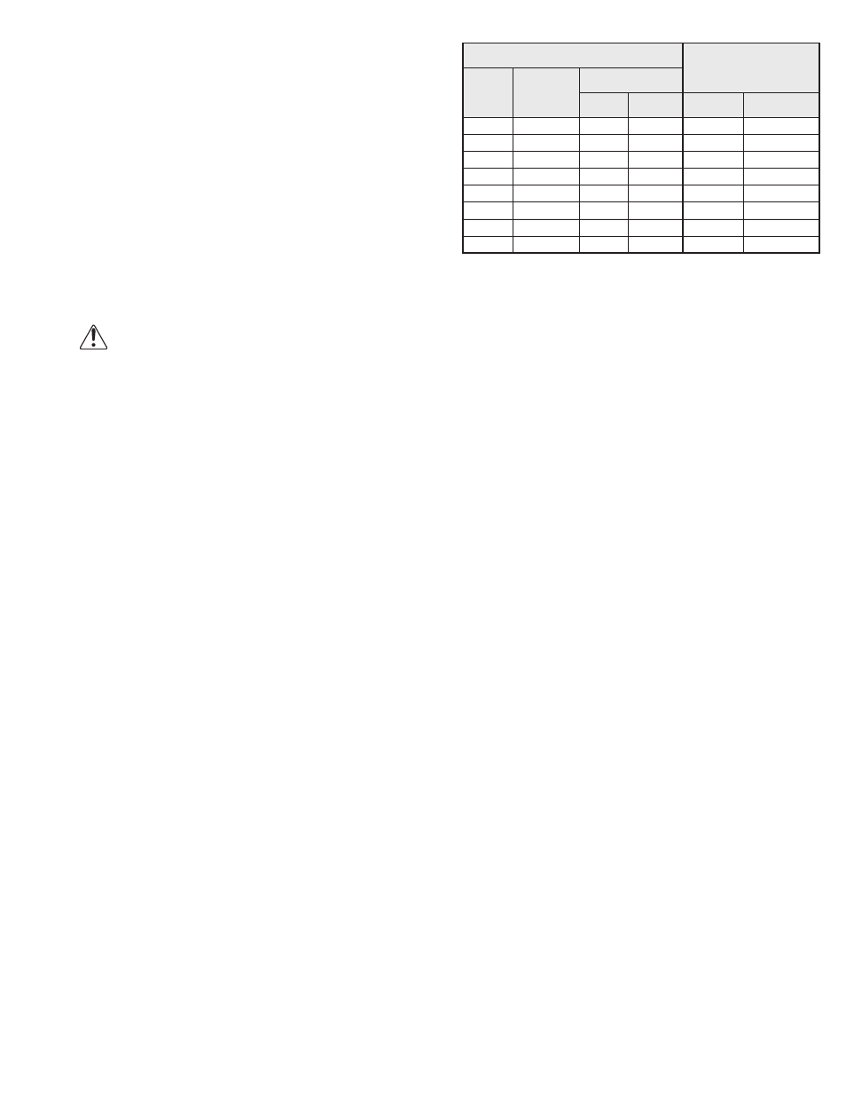
Recommended Torque for Setscrews/Bolts (IN/LB.)
Setscrews
Hold Down Bolts
Size
Key Hex
Across
Flats
Recommended
Torque
Min.
Max.
Size
Wrench
Torque
No.10
3/32”
28
33
3/8”-16
240
1/4”
1/8”
66
80
1/2”-13
600
5/16”
5/32”
126
156
5/8”-11
1200
3/8”
3/16”
228
275
3/4”-10
2100
7/16”
7/32”
348
384
7/8”-9
2040
1/2”
1/4”
504
600
1”-8
3000
5/8”
5/16”
1104
1200
1-1/8”-7
4200
3/4”
3/8”
1440
1800
1-1/4”-7
6000