Motor services, Changing shaft speed, Pulley and belt replacement – COOK PLC User Manual
Page 6: Bearing replacement
6
nance department disassemble and lubricate the bear-
ings after 3 years of operation to prevent interruption of ser-
vice.
For motors with provisions for relubrication, follow inter-
vals of the following table.
Motors are provided with a polyurea mineral oil NGLI #2
grease. All additions to the motor bearings are to be with a
compatable grease such as Exxon Mobil Polyrex EM and
Chevron SRI.
The above intervals should be reduced to half for vertical
shaft installations.
Motor Services
Should the motor prove defective within a one-year
period, contact your local Loren Cook representative or
your nearest authorized electric motor service representa-
tive.
Changing Shaft Speed
All belt driven fans with motors up to and including 5 HP
(184T max.) are equipped with variable pitch pulleys. To
change the fan speed, perform the following:
a. Loosen setscrew on driver (motor) pulley and remove
key, if equipped.
b. Turn the pulley rim to open or close the groove facing.
If the pulley has multiple grooves, all must be adjusted
to the same width.
c. After adjustment, inspect for proper belt tension.
Speed Reduction
Open the pulley in order that the belt rides deeper in the
groove (smaller pitch diameter).
Speed Increase
Close the pulley in order that the belt rides higher in the
groove (larger pitch diameter). Ensure that the RPM
limits of the fan and the horsepower limits of the motor
are maintained.
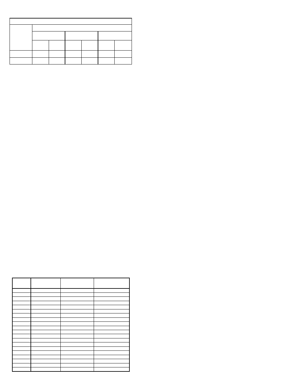
Relubrication Intervals
Service
Conditions
NEMA Frame Size
Up to and
including 184T
213T-365T
404T and larger
1800 RPM
and less
Over 1800
RPM
1800 RPM
and less
Over 1800
RPM
1800 RPM
and less
Over 1800
RPM
Standard
3 yrs.
6 months
2 yrs.
6 months
1 yr.
3 months
Severe
1 yr.
3 months
1 yr.
3 months 6 months
1 months
Pulley and Belt Replacement
a. Remove pulleys from their respective shafts.
b. Clean the motor and fan shafts.
c. Clean bores of pulleys and coat the bores with
heavy oil.
d. Remove grease, rust, or burrs from the pulleys
e. Remove burrs from shaft by sanding.
f. Place fan pulley on fan shaft and motor pulley on
its shaft. Damage to the pulleys can occur when
excessive force is used in placing the pulleys on
their respective shafts.
g. Tighten in place.
h. Install belts on pulleys and align as described in
the Belt and Pulley Installation section.
Bearing Replacement
The fan bearings are pillow block ball bearings.
Bearings should be replaced individually for each side
of fan.
An emery cloth or file may be needed to remove
imperfections in the shaft left by the setscrews.
a. Remove belts.
b. If replacing drive side bearing, mark location of
pulley and remove.
c. Mark bearing location on bearing support and
loosen bearing hold down bolts.
d. Support the shaft to remove weight from bearing.
e. Remove anti-corrosion coating from the shaft with
a suitable degreaser.
f. Remove the bearing from the shaft using a bear-
ing puller. If a bearing puller is not available, tap
on the bearing with a wood block and hammer to
remove it.
g. Smooth and clean the shaft and bearing bore
thoroughly.
h. Place the bearings into position making sure they
are not on a worn section of the shaft. Tapping the
inner ring face with a soft driver may be required.
Do not hammer on the housing.
i. The outer ring of the bearing is spherical and swiv-
els in the housing to compensate for misalign-
ment. Secure hold-down bolts, but do not fully
tighten.
j. Align the setscrews on the bearings and tighten
one setscrew on each bearing.
k. Rotate the shaft to allow the bearing outer rings to
find their center of free movement.
l. Tighten hold-down bolts to proper torque as shown
in the torque chart.
m. Turn the shaft by hand. Resistance should be the
same as it was before hold-down bolts were fully
tightened.
n. Tighten bearing setscrews to specified torque
(see chart).
o. Re-install the pulley and adjust the belt tension.
Refer to Belts and Pulley Installation.
p. Repeat the process for opposite bearing.
q. Adjust the belt tension.
r. Test run and retighten all setscrews and bolts.
Trim balance as necessary (.0785 in/sec max.).
After 24 hours of operation, retighten the setscrews
to the appropriate torque. This assures full locking of
Max Class Speeds of PLC
Size
Class I
Class II
Class III
120
4,165
4,768
-
135
3,642
4,137
-
150
3,232
3,669
-
165
2,800
3,289
-
180
2,532
2,980
4,101
195
2,291
2,722
3,682
210
2,103
2,504
3,333
225
1,939
2,317
3,062
245
1,759
2,112
2,732
270
1,527
1,895
2,400
300
1,346
1,685
2,233
330
1,276
1,558
1,984
365
1,144
1,392
1,772
402
1,091
1,286
1,604
445
965
1,149
1,484
490
885
1,031
1,306
540
782
929
1,190
600
738
843
1,084
660
650
753
959
730
576
658
834