Inspection, Maintenance, Lubrication - fan bearings – COOK PLC User Manual
Page 5: Lubrication - motor bearings
5
• Inspect for cleanliness. Clean exterior surfaces only.
Removing dust and grease on motor housing assures
proper motor cooling. Removing dirt from the wheel
and housing prevent imbalance and damage.
Lubrication - Fan Bearings
Greasable fan bearings are lubricated through a grease
fitting on the bearing and should be lubricated by the
schedule, Lubrication Conditions Chart.
For best results, lubricate the bearing while the fan is in
operation. Pump grease in slowly until a slight bead forms
around the bearing seals. Excessive grease can burst
seals thus reducing bearing life.
Before lubricating, the grease nipple and immediate
vicinity should be thoroughly cleaned without the use of
high pressure equipment. The grease should be supplied
slowly as the bearing rotates until fresh grease slips past
the seal. Excessive pressure should be avoided to prevent
seal damage.
In the event the bearing cannot be seen, use no more
than three injections with a hand-operated grease gun.
Exceptions to the greasing interval chart:
• Periodic Applications (any break of one week or
more): it is recommended that full lubrication be performed
prior to each break in operation.
• Higher Temperature: it is recommended to halve the
intervals for every 30
°F increase in operating temperature
above 120
°F not to exceed 230°F for standard bearings;
High Temperature bearings (optional) can operate up to
400
°F.
• Vertical Shaft: it is recommended that the intervals
should be halved.
Loren Cook Company uses petroleum lubricant in a lith-
ium base. Other types of grease should not be used unless
the bearings and lines have been flushed clean. If another
type of grease is used, it should be a lithium-based grease
conforming to NLGI grade 2 consistency.
A NLGI grade 2 grease is a light viscosity, low-torque,
rust-inhibiting lubricant that is water resistant. Its tempera-
ture range is from -30
°F to +200°F and capable of intermit-
tent highs of +250
°F.
Lubrication - Motor Bearings
Motors are provided with prelubricated bearings. Any
lubrication instructions shown on the motor nameplate
supersede instructions below.
Motor bearings without provisions for relubrication will
operate up to 10 years under normal conditions with no
maintenance. In severe applications, high temperatures or
excessive contaminates, it is advisable to have the mainte-
If a problem is discovered, immediately shut the fan
off. Lock out all electrical power and check for the
cause of the trouble. See Troubleshooting.
Inspection
Inspection of the fan should be conducted at the first 30
minute, 8 hour and 24 hour intervals of satisfactory opera-
tion. During the inspections, stop the fan and inspect as per
the Conditions Chart.
30 Minute Interval
Inspect bolts, setscrews, and motor mounting bolts.
Adjust and tighten as necessary.
8 Hour Interval
Inspect belt alignment and tension. Adjust and tighten as
necessary.
24 Hour Interval
Inspect belt tension, bolts, setscrews, and motor mount-
ing bolts. Adjust and tighten as necessary.
Maintenance
Establish a schedule for inspecting all parts of the fan.
The frequency of inspection depends on the operating con-
ditions and location of the fan.
Inspect fans exhausting corrosive or contaminated air
within the first month of operation. Fans exhausting con-
taminated air (airborne abrasives) should be inspected
every three months.
Regular inspections are recommended for fans exhaust-
ing non-contaminated air.
It is recommended the following inspection be conducted
twice per year.
• Inspect bolts and setscrews for tightness. Tighten as
necessary. Worn setscrews should be replaced imme-
diately.
• Inspect belt wear and alignment. Replace worn belts
with new belts and adjust alignment as needed. Refer
to Belt and Pulley Installation, page 4.
• Bearings should be inspected as recommended in the
Conditions Chart.
• Inspect variable inlet vanes for freedom of operation
and excessive wear. The vane position should agree
with the position of the control arm. As the variable inlet
vanes close, the entering air should spin in the same
direction as the wheel.
• Inspect isolation base for freedom of movement.
• Inspect springs and rubber isolators for deterioration
and replace as needed.
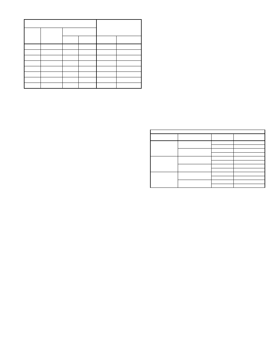
Recommended Torque for Setscrews/Bolts (IN/LB.)
Setscrews
Hold Down Bolts
Size
Key Hex
Across
Flats
Recommended
Torque
Min.
Max.
Size
Wrench
Torque
No.10
3/32”
28
33
3/8”-16
240
1/4”
1/8”
66
80
1/2”-13
600
5/16”
5/32”
126
156
5/8”-11
1200
3/8”
3/16”
228
275
3/4”-10
2100
7/16”
7/32”
348
384
7/8”- 9
2040
1/2”
1/4”
504
600
1”- 8
3000
5/8”
5/16”
1104
1200
1-1/8” - 7
4200
3/4”
3/8”
1440
1800
1-1/4” - 7
6000
Lubrication Conditions Chart
Fan Class
Fan Status
Shaft Size
Maximum Interval
(operational hrs)
Centrifugal Blower
Class I
Normal Conditions
(Clean, Dry & Smooth)
> 1-1/2”
10,000
< 1-1/2”
2,000
Extreme Conditions
(Dirty/Wet/Rough)
> 1-1/2”
2,000
< 1-1/2”
400
Centrifugal Blower
Class II
Normal Conditions
(Clean, Dry & Smooth)
> 2”
7,500
< 2”
1,000
Extreme Conditions
(Dirty/Wet/Rough)
> 2”
1,500
< 2”
200
Centrifugal Blower
Class III
Normal Conditions
(Clean, Dry & Smooth)
> 2”
3,000
< 2”
500
Extreme Conditions
(Dirty/Wet/Rough)
> 2”
500
< 2”
100