Wheel replacement – COOK Lo-Pro User Manual
Page 6
6
e. Slide new bearings onto the shaft to the desired loca-
tion and loosely mount bearings onto the bearing sup-
port. Bearing bolts and setscrews should be loose
enough to allow shaft positioning.
f. Correctly position the wheel and tighten the bearing
bolts securely to the bearing support.
g. Align setscrews bearing to bearing and secure tightly
to the shaft.
NOTICE! Never tighten both pairs of setscrews
before securing bearing mounting bolts. This may dam-
age the shaft.
h. Inspect the wheel position again. If necessary, readjust
by loosening the bearing bolts and setscrews and
repeat from step e.
Wheel Replacement
a. Drill two holes approximately centered between the
shaft and the edge of the hub OD with the following
dimensions:
• 1/4" diameter
• 3/8" to 1/2" deep
• 180° apart in face of hub
b. Tap 1/4" holes to 5/16" thread with the 5/16" hole tap.
Do not drill or tap any larger than recommended.
c. Screw the puller arms into the tapped holes full depth
of threads (3/8" to 1/2" approximately). Align center of
puller with center of shaft. Make certain all setscrews in
hub (normally a quantity of two) are fully removed.
Work puller slowly to back wheel off the shaft.
Recommended Puller
Lisle No. 45000 Sterling Wheel Puller. This puller is avail-
able at most automotive parts retail outlets.
Wheel Replacement Components
Above - Drilled Hole Location
Above - Wheel Puller
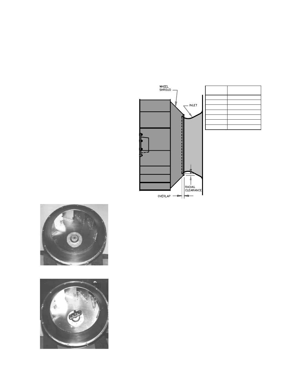
Wheel-to-Inlet Clearance
The correct wheel-to-inlet clearance is critical to proper
fan performance. This clearance should be verified before
initial start-up since rough handling during shipment could
cause a shift in fan components. Refer to wheel/inlet draw-
ing for correct overlap.
Adjust the overlap by loosening the wheel hub and mov-
ing the wheel along the shaft to obtain the correct value.
A uniform radial gap (space between the edge of the
cone and the edge of the inlet) is obtained by loosening the
inlet cone bolts and repositioning the inlet cone.
Size
Maximum Overlap
100 - 165
3/16”
180 - 245
1/4”
270 - 300
5/16”
330 - 365
3/8”
402
7/16”
445 - 490
1/2”
540 13/16”
Wheel/Inlet Overlap