Wiring diagrams, Single speed, single phase motor, Typical damper motor schematic – COOK Lo-Pro User Manual
Page 3
3
Fan
Motor
Damper
Motor*
Second
Damper
Motor
Transformer**
Transformer**
L3
L2
L1
4 5 6
1
7
2
8
3
9
L1 L2 L3
4 5 6
7 8 9
1 2
3
L1 L2 L3
Low Voltage
208/230 Volts
High Voltage
460 Volts
3 Phase, 9 Lead Motor
Y-Connection
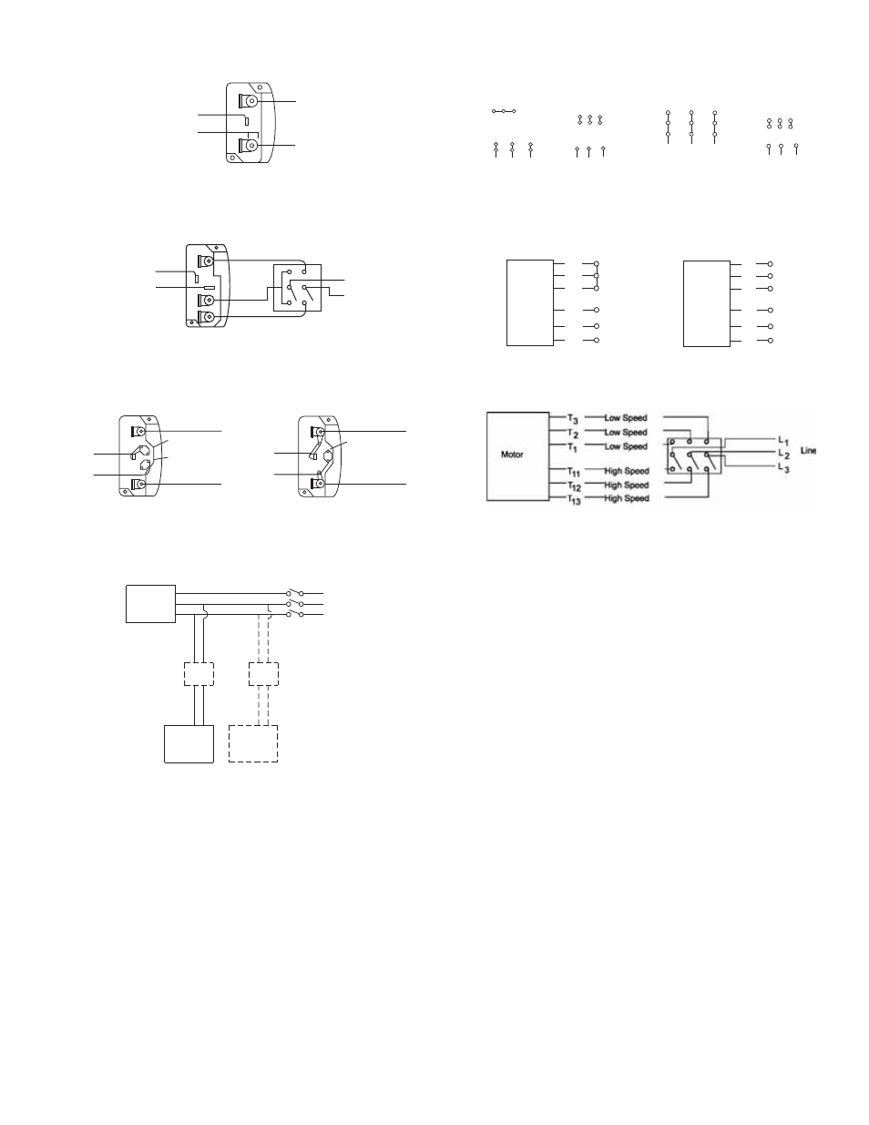
Wiring Diagrams
Wiring Diagrams
When ground is required, attach to ground A or B with no. 6 thread forming
screw. To reverse, interchange T-1 and T-4.
Single Speed, Single Phase Motor
To reverse, interchange any 2 line leads.
When ground required, attach to ground A or B with No. 6 thread forming
screw. To reverse, interchange T-1 and T-4 leads.
2 Speed, 2 Winding, Single Phase Motor
2 Speed, 1 Winding, 3 Phase Motor
To reverse, interchange any 2 line leads. Motors require magnetic control.
Single Speed, Single Phase, Dual Voltage
2 Speed, 2 Winding, 3 Phase
When ground required, attach to ground A or B with No. 6 thread forming
screw. To reverse, interchange T-5 and J-10 leads.
To reverse: High Speed-interchange leads T
11
and T
12
.
Low Speed-interchange leads T
1
and T
2
. Both Speeds-interchange any 2
line leads.
Typical Damper Motor Schematic
For 3 phase, damper motor voltage should be the same between L
1
and
L
2
. For single phase application, disregard L
3
. *Damper motors may be
available in 115, 230 and 460 volt models. The damper motor nameplate
voltage should be verified prior to connection. **A transfomer may be pro-
vided in some installations to correct the damper motor voltage to the
specified voltage.
T-1
T-4
Ground B
L2
L1
Ground A
Line
Ground A
Ground B
T-1
T-4
Low Speed
High Speed
L1
L2
Line
Ground B
J-10
T-5
Ground A
Link A
Link B
Low Voltage
Line
L 2
L 1
Ground A
Link A & B
L1
L 2
Line
Ground B
T-5
J-10
Motor
1
2
3
4
5
6
Together
High Speed
Line
L1
L2
L3
1
2
3
4
5
6
Open
Low Speed
Line
L1
L2
L3
Motor
7
1
6
7 8 9
4 5 6
1 2
3
Low Voltage
208/230 Volts
High Voltage
460 Volts
8
2
4
9
3
5
L1
L3
L2
L1
L3
L2
3 Phase, 9 Lead Motor
Delta-Connection