Operation, Electrical shock & fire hazard, Final installation steps – COOK Gemini User Manual
Page 4
4
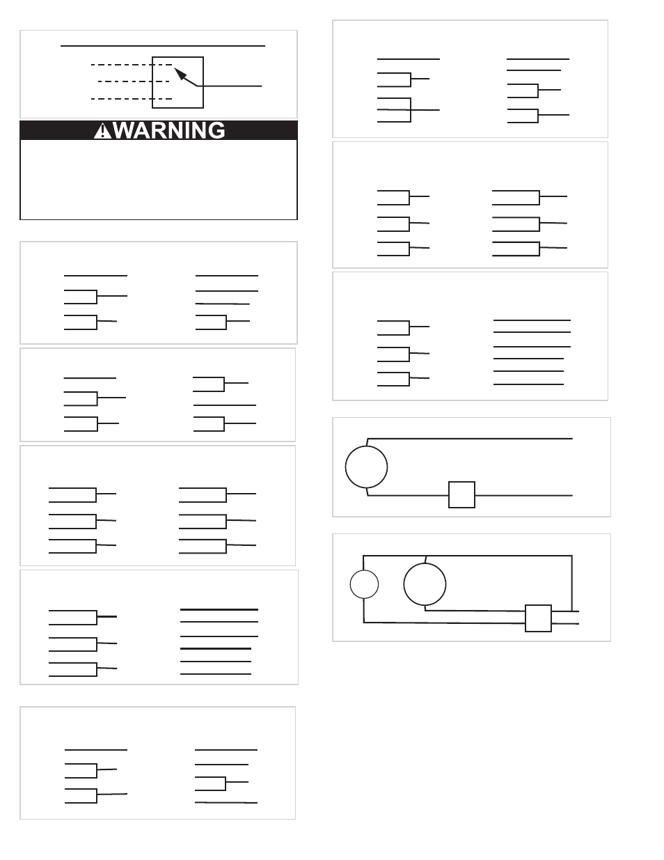
Gemini 800 - 900 Series:
White
Line
Line
Black (High)
Blue (Medium)
Red (Low)
Electrical Shock & Fire Hazard:
Insulate Unused Leads Separately
Failure to follow these instructions could result in
death or serious injury.
Gemini 1000:
White
Line 2
Line 1
Yellow
Purple
Orange
Insulate
Brown
Yellow
Line 2
Line 1
Brown
Purple
Orange
Insulate
Insulate
White
1 PH / 60 HZ / 115V
MARATHON 6.0 AMPS
1 PH / 60 HZ / 208-230 V
MARATHON 2.8-3.0 AMPS
White
Line 2
Line 1
Red
Black
Blue
Insulate
Orange
Yellow
Line 2
Line 1
Insulate
Blue
Purple
Orange
White
1 PH / 60 HZ / 115V
MAGNETEK 8.0 AMPS
1 PH / 60 HZ / 208-230 V
MAGNETEK 4.1 AMPS
T4
Insulate
P4
T5
Insulate
P6
T6
Insulate
P6
T1
T7
T2
T8
T3
T9
3 PH / 60 HZ / 208-230 V
MARATHON 2.2-2.0 AMPS
MAGNETEK 2.2-2.0 AMPS
Line 2
Line 1
Line 3
T4
Insulate
T7
T6
Insulate
T9
T5
Insulate
T8
T1
T2
T3
P4
P5
P6
3 PH / 60 HZ / 460 V
MARATHON 1.0 AMP
MAGNETEK 1.0 AMP
Line 2
Line 1
Line 3
Insulate
Insulate
Insulate
Gemini 2000:
Brown
Line 2
Line 1
Blue
Purple
White
Insulate
Black
Brown
Line 2
Line 1
Blue
Orange
White
Insulate
Insulate
Black
1 PH / 60 HZ / 115V
MARATHON 10.8 AMPS
1 PH / 60 HZ / 208-230 V
MARATHON 6.0-5.4 AMPS
P2
Line 2
Line 1
T3
P1
T2
Insulate
T4
T5
T5
P2
Insulate
Line 1
Insulate
T3
P1
Line 2
T2
T4
1 PH / 60 HZ / 115 V
LEESON 10.2 AMPS
1 PH / 60 HZ / 208-230 V
LEESON 5.2 AMPS
T4
Insulate
P4
T5
Insulate
P6
T6
Insulate
P6
T1
T7
T2
T8
T3
T9
Line 2
Line 1
Line 3
3 PH / 60 HZ / 208-230 V
MARATHON 4.1-4.2 AMPS
LEESON 3.4 AMPS
T4
Insulate
T7
T6
Insulate
T9
T5
Insulate
T8
T1
T2
T3
P4
P5
T6
3 PH / 60 HZ / 460 V
MARATHON 2.1 AMPS
LEESON 1.7 AMPS
Line 2
Line 1
Line 3
Insulate
Insulate
Insulate
FSC:
White
Fan
Black
FSC
Time Delay Switch:
White
Black
Red
Blue
Fan
light
Switch
Final Installation Steps
1. Inspect fasteners and setscrews, particularly fan
mounting fasteners, and tighten as required.
2. Inspect for correct amperage and voltage with an
ammeter and voltmeter.
3. Ensure blower is secured to duct work.
4. Ensure all accessories are installed.
5. Inspect wheel-to-inlet clearance. Make sure wheel
does not rub against the inlet.
6. Test the fan to be sure the rotation is the same as
indicated by the arrow marked Rotation.
Grille installation is described after the operation
and inspection sections.