Wiring installation, Wiring diagrams, Electrical shock & fire hazard – COOK Gemini User Manual
Page 3
3
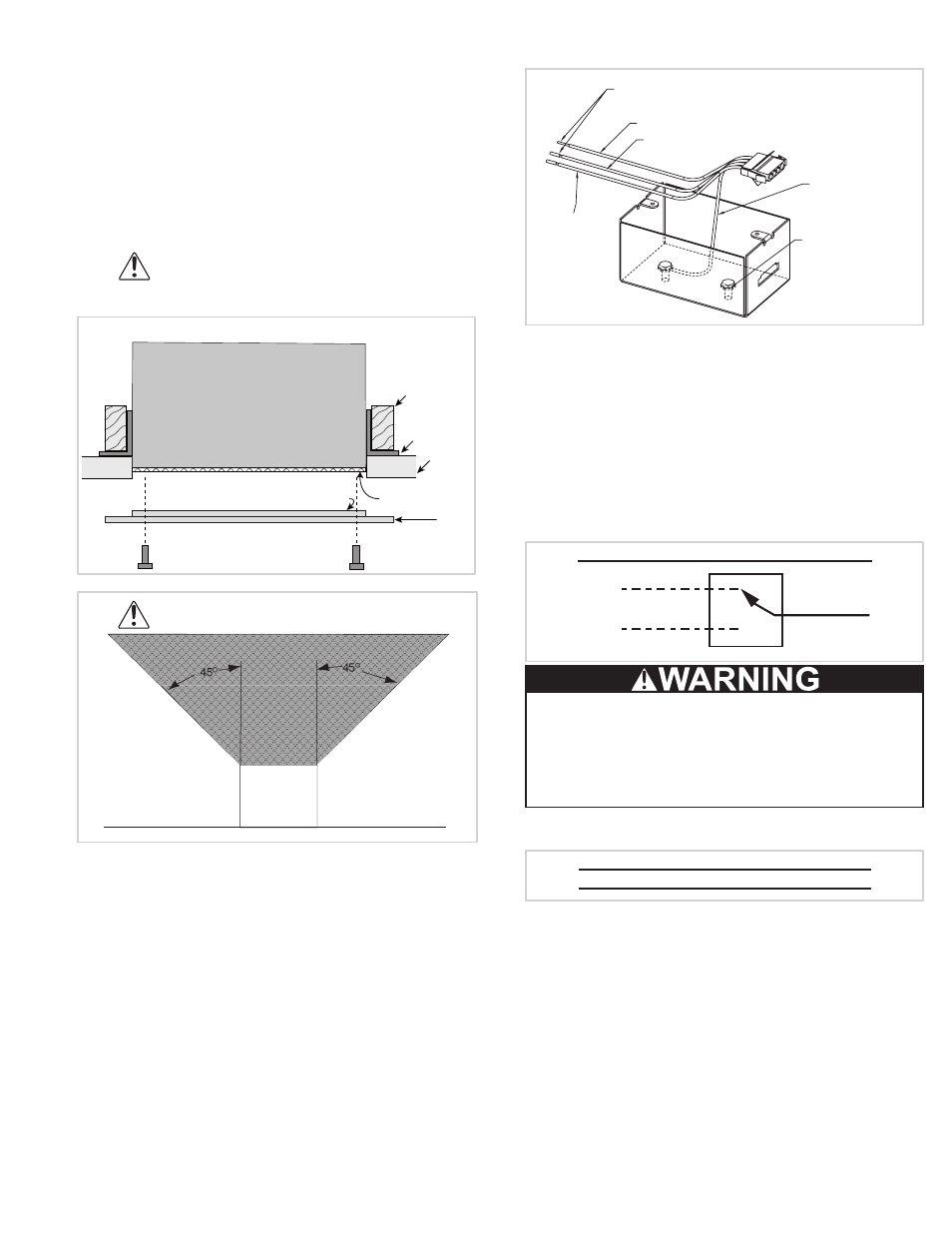
unit 3/8”. If filter and deluxe aluminum grille are
both present, raise unit 7/8”, due to the 1/2” grate
protrusion on the aluminum grille. If filter is not
present: the grate on the aluminum grille will fit inside
of the unit (except sizes 160 & 180). Other grilles have
no protrusion and fit flush with the fan.
3. Fasten duct work to the outside of the duct collar
(damper frame) using sheet metal screws and foil
tape. Make sure sheet metal screws are placed
where they do not interfere with damper operation.
4. Fasten the housing to the bottom of the joists
through the holes provided in the mounting bracket.
For Ceiling Radiation Damper Installation
see separate document “Gemini/CRD
Installation Supplement.”
Mounting
Bracket
Filter (optional)
Ceiling
Grille
Joists
Unit Housing
Grate Protrusion
(aluminum grille only)
45
O
Cooking
Equipment
Floor
45
O
Wiring Installation
All wiring should be in accordance with local
ordinances and the National Electrical Code, NFPA 70.
Ensure the power supply (voltage, frequency, and current
carrying capacity of wires) is in accordance with the
motor nameplate. Refer to Wiring Diagrams.
Lock out all power sources before unit is wired to power
source.
Follow the wiring diagram in the disconnect switch and
the wiring diagram provided with the motor. Correctly
label the circuit on the main power box and always
identify a closed switch to promote safety (i.e., red tape
over a closed switch).
Note: Insulate Unused Leads. Fan plug box is designed
for single speed operation, using an FSC to vary speed if
required. Do not wire to more than two leads.
Wiring Diagrams
Gemini 100 Series:
Cap off wire that is not in use.
Ground Screw for
Field Grounding
Green Wire
(Ground by COOK)
Black Wire (High Speed)
Red Wire (Low Speed)
White Wire
(Common)
For fan power supply connection use 4-wire cable
provided in field wiring box shown above. Connect field
ground wire to green ground screw located inside fan
electrical box. Connect one supply line to white wire.
Depending on fan speed requirements connect other
supply line to Red wire for Low Speed or Black wire
for High Speed. Insulate unused Red or Black wire.
Replace electrical box cover. Model 126, 146, 166, 186
are Low Speed. Models 128, 148, 168, 188 are High
Speed.
Gemini 200, 300, 500, 600 and 700 Series:
White
Line
Line
Black (High)
Red (Low)
Electrical Shock & Fire Hazard:
Insulate Unused Lead
Failure to follow these instructions could result in
death or serious injury.
Gemini 400 Series:
White
Line
Black
Line
Wiring continued on the next page.
Notice! Do not install above or around
cooking equipment (shaded area)
Figure 2