Belt and pulley, Belt and pulley installation, Wiring diagrams – COOK Duct Blower User Manual
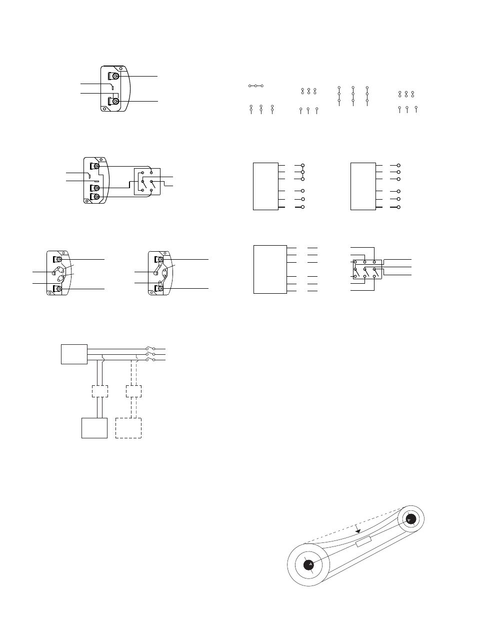
Page 2: Single speed, single phase motor, Typical damper motor schematic
2
1 foot
1/4 inch
For proper tension, a deflection of approximately 1/4”
per foot of center distance should be obtained by
firmly pressing the belt. Refer to Figure 1.
c. Lock the motor plate adjustment nuts in place.
d. Ensure pulleys are properly aligned. Refer to Figure 2.
4 5 6
1
7
2
8
3
9
L1 L2 L3
4 5 6
7 8 9
1 2
3
L1 L2 L3
Low Voltage
208/230 Volts
High Voltage
460 Volts
3 Phase, 9 Lead Motor
Y-Connection
7
1
6
7 8 9
4 5 6
1 2
3
Low Voltage
208/230 Volts
High Voltage
460 Volts
8
2
4
9
3
5
L1
L3
L2
L1
L3
L2
3 Phase, 9 Lead Motor
Delta-Connection
Figure 1
Fan
Motor
Damper
Motor*
Second
Damper
Motor
Transformer**
Transformer**
L3
L2
L1
Belt and Pulley Installation
Belt tension is determined by the sound of the belts when
the fan is first started. The belts will produce a loud squeal,
which dissipates after the fan is operating at full capacity. If
belt tension is too tight or too loose, lost efficiency and
damage can occur.
Do not change the pulley pitch diameter to change ten-
sion. The change will result in a different fan speed.
Models SDB
a. Loosen the motor plate bolts and move the motor
plate (with motor installed) so that the belts can easily
slip into the grooves on the pulleys. Never pry, roll, or
force the belts over the rim of the pulley.
b. Adjust the motor plate until proper tension is reached.
Wiring Diagrams
Wiring Diagrams
When ground is required, attach to ground A or B with no. 6 thread forming
screw. To reverse, interchange T-1 and T-4.
Ground A
L
1
L
2
Line
T-1
T-4
Ground B
Single Speed, Single Phase Motor
To reverse, interchange any 2 line leads.
When ground required, attach to ground A or B with No. 6 thread forming
screw. To reverse, interchange T-1 and T-4 leads.
T-1
T-4
Ground B
Ground A
High Speed
Low Speed
L
1
L
2
Line
2 Speed, 2 Winding, Single Phase Motor
2 Speed, 1 Winding, 3 Phase Motor
To reverse, interchange any 2 line leads. Motors require magnetic control.
Together
Open
Low Speed
High Speed
Motor
Motor
1
2
3
4
5
6
L
1
L
2
L
3
L
1
L
2
L
3
1
2
3
4
5
6
Single Speed, Single Phase, Dual Voltage
2 Speed, 2 Winding, 3 Phase
When ground required, attach to ground A or B with No. 6 thread forming
screw. To reverse, interchange T-5 and J-10 leads.
Link A
Low Voltage
Ground A
Ground B
T-5
J-10
L
1
L
2
Line
T-5
J-10
Ground A
Ground B
Link A & B
High Voltage
L
1
L
2
Line
Link B
To reverse: High Speed-interchange leads T
11
and T
12
.
Low Speed-interchange leads T
1
and T
2
. Both Speeds-interchange any 2
line leads.
T
3
T
2
T
1
T
11
T
12
T
13
Low Speed
Low Speed
Low Speed
High Speed
High Speed
High Speed
L
1
L
2
L
3
Motor
Typical Damper Motor Schematic
For 3 phase, damper motor voltage should be the same between L
1
and
L
2
. For single phase application, disregard L
3
. *Damper motors may be
available in 115, 230 and 460 volt models. The damper motor nameplate
voltage should be verified prior to connection. ** A transformer may be pro-
vided in some installations to correct the damper motor voltage to the
specified voltage.
Line
Line
Line
Follow the wiring diagram in the disconnect switch and the wiring diagram provided with the motor. Correctly label the circuit
on the main power box and always identify a closed switch to promote safety (i.e., red tape over a closed switch).