Final installation steps, Operation, Start up – COOK AVA User Manual
Page 6: Inspection, Maintenance, Prop rotation, Recommended torque for setscrews/bolts
6
change two leads at this location so that the fan is
operating in the correct direction.
Final Installation Steps
a. Inspect fasteners and setscrews, particularly fan
mounting and bearing fasteners, and tighten according
to the recommended torque shown in the table Recom-
mended Torque for Setscrews/Bolts.
b. Inspect for correct voltage with voltmeter.
c. Ensure all accessories are installed.
Operation
Pre-Start Checks
a. Lock out all the primary and secondary power sources.
b. Ensure fasteners and setscrews, particularly those
used for mounting the fan, are tightened.
c. Inspect belt tension and pulley alignment.
d. Inspect motor wiring.
e. Ensure belt touches only the pulley.
f. Ensure fan and ductwork are clean and free of debris.
g. Inspect prop-to-inlet clearance. The correct prop-to-
inlet clearance is critical to proper fan performance.
h. Close and secure all access doors.
i. Restore power to the fan.
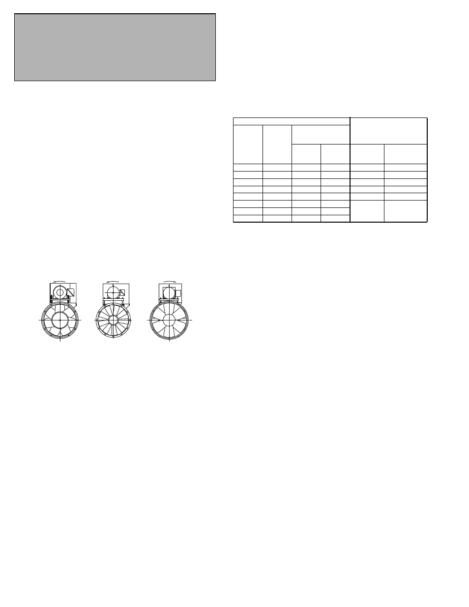
Rotation
VAB/VAHB
Rotation
AVAB
Rotation
AFB
Prop Side
Prop Side
Prop Side
Start Up
Turn the fan on. In variable speed units, set the fan to
its lowest speed and inspect for the following:
• Direction of rotation.
• Excessive vibration.
• Unusual noise.
• Bearing noise.
• Improper belt alignment or tension (listen for squeal-
ing).
• Improper motor amperage or voltage.
If a problem is discovered, immediately shut the
fan off. Lock out all electrical power and check for the
cause of the trouble. See Troubleshooting.
Inspection
Inspection of the fan should be conducted at the first 30
minute, 8 hour and 24 hour intervals of satisfactory
operation. During the inspections, stop the fan and
inspect as per the Conditions Chart.
30 Minute Interval
Inspect bolts, setscrews, and motor mounting bolts.
Adjust and tighten as necessary.
8 Hour Interval
Inspect belt alignment and tension. Adjust and tighten
as necessary.
24 Hour Interval
Inspect belt tension. Adjust and tighten as necessary.
Maintenance
Establish a schedule for inspecting all parts of the fan.
The frequency of inspection depends on the operating
conditions and location of the fan.
Inspect fans exhausting corrosive or contaminated air
within the first month of operation. Fans exhausting con-
taminated air (airborne abrasives) should be inspected
every three months.
Regular inspections are recommended for fans
exhausting non-contaminated air.
It is recommended the following inspection be con-
ducted twice per year.
• Inspect bolts and setscrews for tightness. Tighten as
necessary.
• Inspect belt wear and alignment. Replace worn belts
with new belts and adjust alignment as needed.
Refer to Belt and Pulley Installation, page 3.
• Bearings should be inspected as recommended in
the Conditions Chart on page 6.
Prop Rotation
Test the fan to ensure the rotation of the wheel is the
same as indicated by the arrow marked Rotation.
115 and 230 Single Phase Motors
Fan wheel rotation is set correctly at the factory. Chang-
ing the rotation of this type of motor should only be
attempted by a qualified electrician.
208, 230, and 460, 3 Phase Motors
These motors are electrically reversible by switching two
of the supply leads. For this reason, the rotation of the fan
cannot be restricted to one direction at the factory. See Wir-
ing Diagrams for specific information on reversing wheel
direction.
Do not allow the fan to run in the wrong direction. This
will overheat the motor and cause serious damage. For
3-phase motors, if the fan is running in the wrong direc-
tion, check the control switch. It is possible to inter-
Recommended Torque for Setscrews/Bolts
Setscrews
Hold Down Bolts
Size
Key Hex
Across
Flats
Recommended
Torque
Inch-lbs.
Min.
Max.
Size
Wrench
Torque
(inch-lbs)
No.10
3/32”
28
33
3/8”-16
240
1/4”
1/8”
66
80
1/2”-13
600
5/16”
5/32”
126
156
5/8”-11
1200
3/8”
3/16”
228
275
3/4”-10
2100
7/16”
7/32”
29
348
7/8”-9
2040
1/2”
1/4”
42
504
-
-
5/8”
5/16”
92
1104
3/4”
3/8”
120
1440
Personal Safety
Disconnect switches are recommended. Place the
disconnect switch near the fan in order that the
power can be swiftly cut off in case of an emergency,
and in order that maintenance personnel are
provided complete control of the power source.