Duct installation, Min 1 dia, Isolation installation – COOK AVA User Manual
Page 2
2
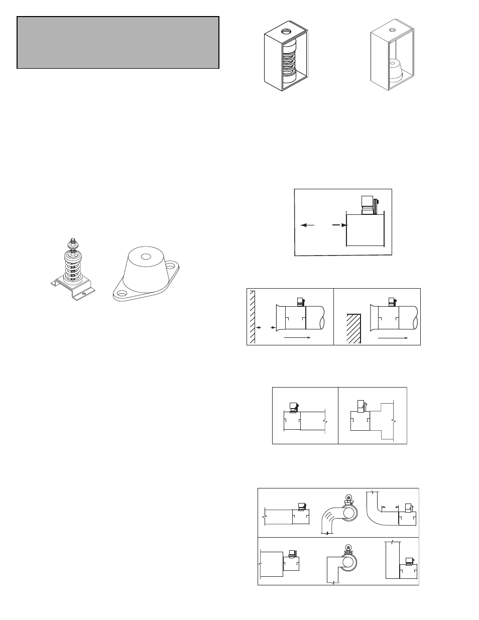
Duct Installation
Efficient fan performance relies on the proper installation
of inlet and discharge ducts. Be sure your fan conforms to
the guidelines below.
Non-Ducted Inlet Clearance
If your fan has an open inlet (no duct work), the fan must
be placed one fan wheel diameter away from walls and
bulkheads.
Free Discharge
Avoid a free discharge into the plenum. This will result in
lost efficiency because it doesn’t allow for a static regain.
Inlet Duct Turns
For ducted inlets, allow at least 3 fan wheel diameters
between duct turns or elbows and the fan inlet.
Rubber-In-Shear Ceiling Isolators
Ceiling Mounted Spring Isolator
Figure 2 - Ceiling Mount Isolators
Non-ducted Inlet Clearance
MIN
1 DIA
Inlet Bell
Air Flow
Correct
Inlet Bell
Fan
Inlet Bell
Air Flow
Incorrect
Fan
Min
1 Dia.
Free Discharge
Correct
Incorrect
Correct
Incorrect
MIN
3 DIA
Inlet Duct Turns
Correct
Incorrect
Min 3
Dia
I l t D
t T
Isolation Installation
Floor Mounted Spring Isolators
a. Mount fan and motor on unitary base (if supplied).
b. Elevate fan (or isolation base) to operating height and
insert blocks to hold in position.
c. Position isolators under the fan and vertically align by
inserting leveling bolt through mounting holes in the fan or
the base. The isolator must be installed on a level surface.
d. Adjust the isolators by turning the leveling nut counter
clockwise several turns at a time alternately on each isola-
tor until the fan weight is transferred onto the isolators and
the fan raises uniformly off the blocks. Then remove the
blocks.
e. Turn lock nut onto leveling bolt and secure firmly in place
against the top of the mounting flange or frame.
f. Secure isolators to mounting surface.
Floor Mounted Rubber-In-Shear (RIS) Isolators
a. Mount fan and motor on a unitary isolation base (if sup-
plied).
b. Elevate fan to provide room to insert isolators between the
fan and foundation and block in position.
c. Position isolators under fan and secure bolts.
d. Remove blocks and allow fan to rest on floor. Isolators
must be installed on a level surface (leveling should not be
required).
e. Secure isolators to mounting surface.
Ceiling Mounted Spring and Rubber-in-Shear (RIS) Isola-
tors
a. Elevate fan to operating height and brace.
b. Attach threaded rod to overhead support structure directly
above each mounting hole. Rod should extend to within a
few feet of fan.
c. Attach isolator to end of threaded rod using a nut on each
side of isolator bracket.
d. Insert another section of threaded rod through the fan
mounting hole and isolator.
e. Attach two nuts to threaded rod in isolator.
f. Place adjusting nut and locking nut on threaded rod near
fan mounting bracket.
g. Alternately rotate adjusting nut at each mounting location
until the fan weight is uniformly transferred to the isolators.
Remove bracing.
Note
Extreme vibration is a serious problem that may
cause structural and mechanical failure. To help
vibration and noise from being transferred to the
building, isolators are recommended.
Figure 1 -Floor Mount Isolators
Rubber-In-Shear Isolator
Spring Isolator