Final steps, Operation, Start – COOK AC User Manual
Page 3: Inspection, Maintenance, Final installation steps, Start-up, 30 minute interval, 8 hour interval, 24 hour interval
3
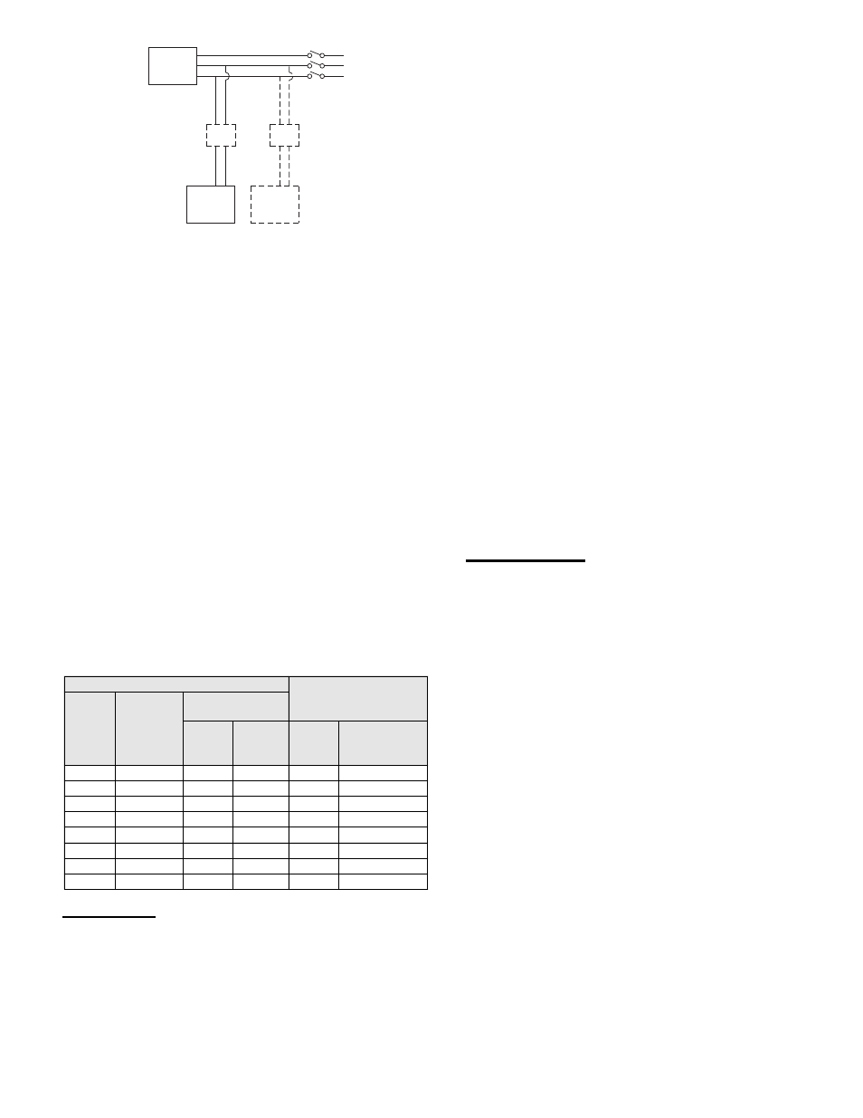
Typical Damper Motor Schematic
For 3 phase, damper motor voltage should be the same between L
1
and L
2
.
For single phase application, disregard L
3
. *Damper motors may be available
in 115, 230 and 460 volt models. The damper motor nameplate voltage
should be verified prior to connection. ** A transformer may be provided in
some installations to correct the damper motor voltage to the specified volt-
age.
Final Installation Steps
1. Ensure fasteners and set screws, particularly fan
mounting and bearing fasteners are tightened according
to the recommended torque shown on the table below.
2. Inspect for correct amperage with an ammeter and
correct voltage with a voltmeter.
3. Ensure that all accessories are installed.
4. Test the fan to be sure the rotation is the same as
indicated by the arrow marked ‘Rotation’.
NOTICE! Do not allow the fan to run in the wrong
direction. This will overheat the motor and cause
serious damage. For 3-phase motors, if the fan is
running in the wrong direction, check the control
switch. It is possible to interchange two leads at this
location so that the fan is operating in the correct
direction.
5. Inspect wheel-to-inlet clearance. Wheels may shift in
shipment. To realign wheel-to-inlet, shift upper bearing
so there is an equal radial clearance between the wheel
and inlet. Refer to wheel to inlet clearance on page 6.
Operation
1. Lock out all the primary and secondary power sources.
2. Inspect and tighten fasteners and setscrews, particularly
fan mounting and bearing fasteners Refer to Torque
chart.
3. Inspect belt tension and pulley alignment. Refer to Belt
and Pulley Installation, page 4.
4. Inspect motor wiring. Refer to Wiring Installation.
5. Ensure belt touches only the pulleys.
6. Rotate the wheel to ensure it rotates freely.
Fan
Motor
Damper
Motor*
Second
Damper
Motor
Transformer**
Transformer**
L3
L2
L1
Recommended Torque for Setscrews/Bolts (IN/LB)
Setscrews
Hold Down Bolts
Size
Key Hex
Across
Flats
Recommended
Torque Inch-lbs.
Min.
Max.
Size
Wrench
Torque (inch-
lbs)
No.10
3/32”
28
33
3/8”-16
240
1/4”
1/8”
66
80
1/2”-13
600
5/16”
5/32”
126
156
5/8”-11
1200
3/8”
3/16”
228
275
3/4”-10
2100
7/16”
7/32”
348
384
7/8”-9
2040
1/2”
1/4”
504
600
1”-8
3000
5/8”
5/16”
1104
1200
1-1/8”-7
4200
3/4”
3/8”
1440
1800
1-1/4”-7
6000
7. Ensure fan and ductwork are clean and free of debris.
8. Close and secure all access doors.
9. Restore power to fan.
Start-up
Turn on the fan. In variable speed units, set the fan to its
lowest speed. Inspect for the following:
• Direction of rotation
• Excessive vibration
• Unusual noise
• Bearing noise
• Improper belt alignment or tension (listen for squealing)
• Improper motor amperage or voltage
If a problem is discovered, immediately shut the fan
off. Lock out all electrical power and check for the cause
of the trouble. Refer to Troubleshooting on page 6.
Inspection
Inspection of the fan should be conducted at the first 30
minute, 8 hour and 24 hour intervals of satisfactory
operation. During the inspections, stop the fan and inspect
as instructed.
30 Minute Interval
Inspect bolts, setscrews, and motor mounting bolts. Adjust
and tighten as necessary.
8 Hour Interval
Inspect belt alignment and tension. Adjust and tighten as
necessary.
24 Hour Interval
Inspect belt tension. Adjust and tighten as necessary.
Maintenance
Establish a schedule for inspecting all parts of the fan. The
frequency of inspection depends on the operating conditions
and location of the fan.
Inspect fans exhausting corrosive or contaminated air
within the first month of operation. Fans exhausting
contaminated air should be inspected every three months.
Regular inspections are recommended for fans exhausting
non-contaminated air.
Regular inspections of the Grease Terminator 2 are
recommended. Depending on the amount of grease
discharged through the fan, the Grease Terminator 2 should
be changed every 30 to 45 days to ensure proper operation.
Any buildup of grease is easily seen during a visual
inspection of the clear canister. However, if the Grease
Terminator 2 becomes saturated, grease will no longer be
absorbed.
It is recommended the following inspections be conducted
twice per year.
• Inspect bolts and setscrews for tightness. Tighten as
necessary. Refer to Torque chart.
• Inspect belt wear and alignment. Replace worn belts with
new belts and adjust alignment as needed. Refer to Belt
and Pulley Installation, page 4.
• Bearings should be inspected as recommended in the
Conditions Chart.
• Inspect for cleanliness. Clean exterior surfaces only.
Removing dust and grease on motor housing assures
proper motor cooling.