Wall exhauster, Damper, Wiring – COOK AC User Manual
Page 2: Wall exhauster installation, Damper installation, Wiring installation
2
Wall Exhauster Installation
If your fan is a wall exhauster, a mounting template is
shipped with the fan. Use the template to locate the
necessary lag screws or anchor bolts on the wall. The fan
can then be lifted and attached easily. Secure with lag
screws, anchor bolts, or other suitable fasteners.
Damper Installation
If your fan is supplied with dampers, follow the directions
below. If your fan does not include dampers, proceed to
Belt and Pulley Installation.
1. Place the damper inside the curb or inside the duct
work. Ensure the damper will open freely for the correct
direction of the airflow.
2. Secure to curb at the damper shelf.
3. Drill hole in the curb shelf for conduit needed for motor
wiring.
4. Operate the dampers manually to ensure the blades
move freely.
5. Install fan over curb while aligning the conduit location
with the conduit hole in the curb.
Wiring Installation
NOTICE! All wiring should be in accordance
with local ordinances and the National Electrical
Code, NFPA 70. Ensure the power supply
(voltage, frequency, and current carrying
capacity of wires) is in accordance with the
motor nameplate.
(See page 3 for diagram)
Upblast units have two wiring conduits. The vertical
conduit comes plugged. The horizontal conduit is directly
above the vertical conduit
For Units Without A Junction Box:
An approved metal field wiring compartment must be
secured to the unit with two screws in order that the box
does not rotate. All wires must be protected from abrasion
where they enter and exit the wiring compartment. The
green ground wire from the motor must be secured under
the green ground screws inside the field wiring compartment
using a closed loop connector. Complete connections in
accordance with the wiring diagram on the motor.
For Units With A Junction Box:
Pull wires through the appropriate conduit. Protect wires
from abrasion where they enter the field wiring compartment
and complete connections in accordance with the diagram
on the motor.
Leave enough slack in the wiring to allow for motor
movement when adjusting belt tension. Some fractional
motors have to be removed in order to make the connection
with the terminal box at the end of the motor.
NOTICE! Follow the wiring diagram in the disconnect
switch and the wiring diagram provided with the motor.
Correctly label the circuit on the main power box and
always identify a closed switch to promote safety (i.e.,
red tape over a closed switch).
1. Remove the top cap which covers the motor assembly
by unlatching the snap clips.
2. For internal wiring, run the electrical wire and conduit
through the opening drilled in the damper shelf (refer to
Damper Installation), then through the wiring conduit in
the ventilator base to the motor compartment. For
external wiring, run the wires through the horizontal
conduit on upblast units, or under top cap in downblast
units.
3. Pull the wires through and complete the wiring.
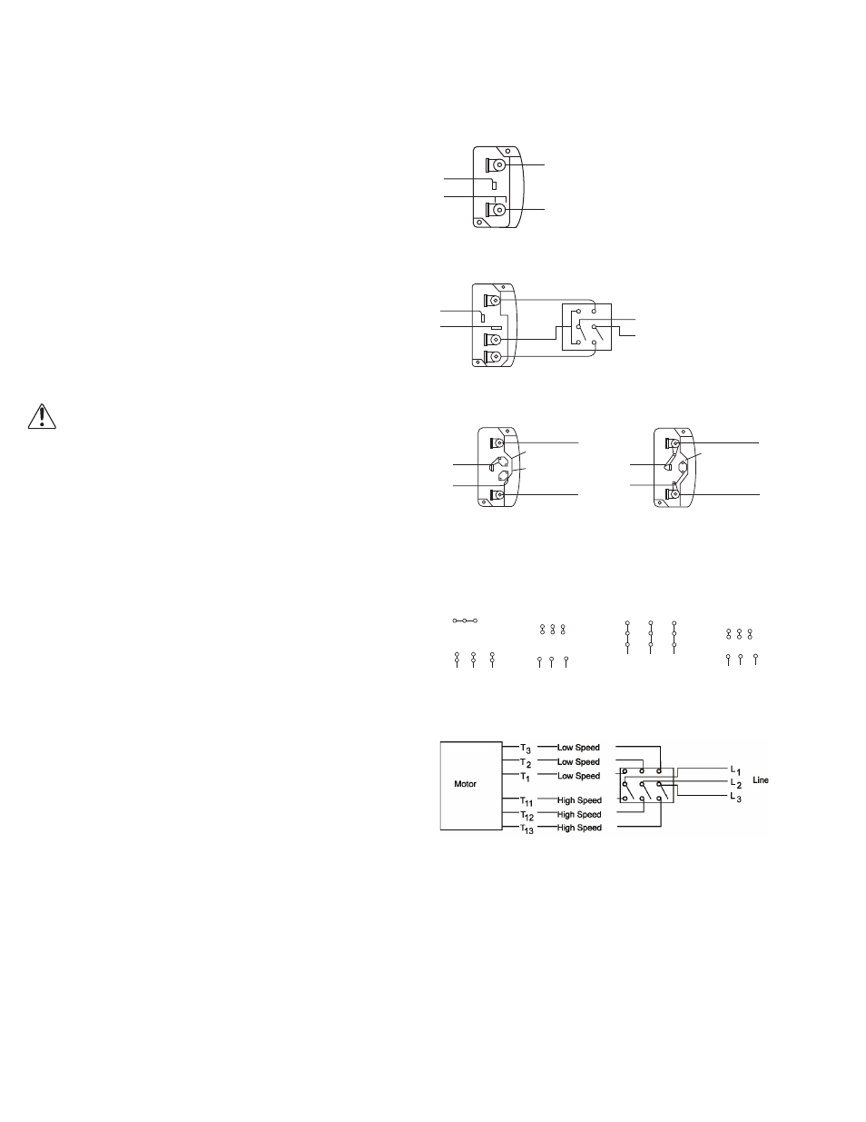
Single Speed, Single Phase Motor
2 Speed, 2 Winding, Single Phase Motor
Single Speed, Single Phase, Dual Voltage
When ground required, attach to ground A or B with No. 6 thread forming screw. To
reverse, interchange T-5 and J-10 leads.
To reverse, interchange any 2 line leads.
2 Speed, 2 Winding, 3 Phase
To reverse: High Speed-interchange leads T
11
and T
12
.
Low Speed-interchange leads T
1
and T
2
. Both Speeds-interchange any 2 line leads.
T-1
T-4
Ground B
L 2
L1
Ground A
Line
When ground required,
attach to ground A or B
with No. 6 thread forming
screw. To reverse, inter-
change T-1 and T-4
leads.
Ground A
Ground B
T-1
T-4
Low Speed
High Speed
L 1
L 2
Line
Ground B
J-10
T-5
Ground A
Link A
Link B
Low Voltage
Line
L 2
L 1
Ground A
Link A & B
L1
L 2
Line
Ground B
T-5
J-10
4 5 6
1
7
2
8
3
9
L1 L2 L3
4 5 6
7 8 9
1 2
3
L1 L2 L3
Low Voltage
208/230 Volts
High Voltage
460 Volts
3 Phase, 9 Lead Motor
Y-Connection
7
1
6
7 8 9
4 5 6
1 2
3
Low Voltage
208/230 Volts
High Voltage
460 Volts
8
2
4
9
3
5
L1
L3
L2
L1
L3
L2
3 Phase, 9 Lead Motor
Delta-Connection
When ground is required, attach to ground A or
B with no. 6 thread forming screw. To reverse,
interchange T-1 and T-4.