Revolution, Setup 5-16, Setup 5-32 – Balboa Water Group Revolution User Manual
Page 67: Transforming the control of hot tubs, Software configuration changes based on default, Power requirements, System ouputs - 16a service, Wiring diagram and settings, Feature orig. setup 1 changes to, System ouputs - 32a service
Revolution
Transforming the Control of Hot Tubs
67
Manufactured under one or more of these patents. U.S. Patents: 5332944, 5361215, 5550753, 5559720, 5,883,459, 6253227, 6282370, 6590188, 6976052, 6965815, 7030343, 7,417,
834 b2, Canadian Patent: 2342614, Australian patent: 2373248 other patents both foreign and domestic applied for and pending. All material copyright of Balboa Water Group.
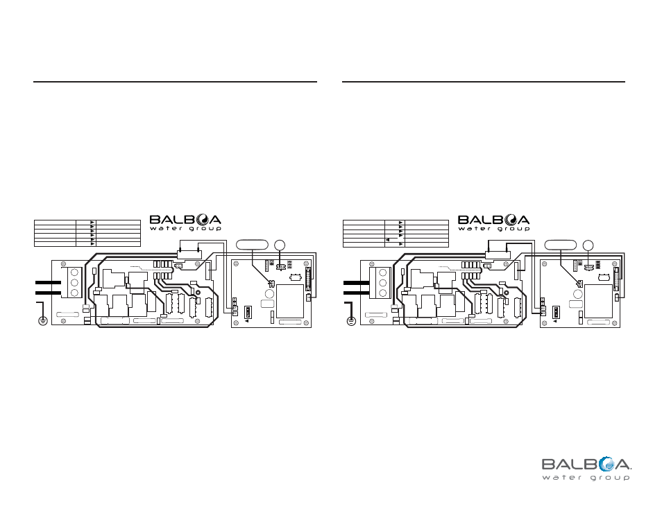
Power Requirements:
Single Service [3 wires (line, neutral, ground)]
230VAC, 50Hz, 1þ, 16A, (Circuit Breaker rating = 20A max.)
System Ouputs - 16A Service:
Pump 1
230VAC
2-Speed
12A max
30-minute timer for Low Speed, 15 Minutes for High Speed
This is the heater pump
Must deliver a minimum of 20 GPM through heater
Low Speed may not exceed 2A max
Ozone
230VAC
.5A max
Uses the same relay as Pump 1 Low
Spa Light
10VAC
On/Off
1A max
4-Hour timer.
Heater
3kW @ 240VAC
Wiring Diagram and Settings
Setup 5-16
Software Configuration Changes based on Default
Feature
Orig. Setup 1
Changes to
J14, TP600 Button 2, TP400 Button 4, LED 2, AX10A2 . . . . . . . . . Pump 2 . . . . . . . . . . . . . . . . . .
Not Used
Blue indicates changes from the original Setup 1 default
J15: SPA LIGHT
BELEUCHTUNG
ECLAIRAGE BAIN HYDRO
10VAC .25A LED
WS05CE
FOR SUPPLY CONNECTIONS,
USE CONDUCTORS SIZED ON THE
BASIS OF 60°C AMPACITY BUT
RATED MINIMUM OF 90°C.
TORQUE RANGE FOR MAIN TERMINAL BLOCK (TB1):
27-30 IN. LBS. (31.1-34.5 kg cm)
USE COPPER CONDUCTORS ONLY
EMPLOYER UNIQUEMENT
DES CONDUCTEURS DE CUIVRE.
L2
L1
N
F3 10A 250V
F2 3A 250V
J44
J48
J1
J2
J24
J45
J49
J15
J16
J47
J13
J27 J25 J26 J23 J33
J28 J30 J31 J32 J29
J12
J46
J20
J57
J8
J14
J22
J21
J56
GND
K3
K5
K6
K2
K1
K4
OZONE
22117_B
RED AC
GND
GND
WHT AC
HTR A
HTR B
UNFUSED
T 150mA
250V
F5 T 30A
S1
J45
J46
F4 3A 250V
J18
J19
K7
T1
J15
J33
J31 HCE
J30 TST
J27
H3
J22
J26 H2
J25 H1
J17
J16
J29 VAC
J28 AUX FRZ
J5
LIGHT
ON
22121_E
1
6
CONTROL PANEL
TO J33
AUX
TO J5
ALL UNUSED SWITCHES SHOULD BE OFF
STORE SETTINGS*
SPECIAL AMPERAGE RULE OFF
DON’T ADD 4 HS PUMPS W/HTR
DON’T ADD 2 HS PUMPS W/HTR
DON’T ADD 1 HS PUMP W/HTR
TEST MODE OFF
MEMORY RESET*
SPECIAL AMPERAGE RULE ON
ADD 4 HS PUMPS WITH HEAT
ADD 2 HS PUMPS WITH HEAT
ADD 1 HS PUMP WITH HEAT
TEST MODE ON
6
5
4
3
2
1
ON POSITION
S1 SWITCH #
OFF POSITION
*SWITCH #
6
SHOULD BE SET TO OFF
UPON FINAL INSTALLATION.
SENSOR A
SENSOR B
NOT USED
2S PUMP 1
NOT USED
GRN
3.0 kW
HEATER
HEIZELEMENT
RADIATEUR
N
L1
N/A
ADDED JUMPER FOR
CE INSTALLATIONS
BLU
BRN
Power Requirements:
Single Service [3 wires (line, neutral, ground)]
230VAC, 50Hz, 1þ, 32A, (Circuit Breaker rating = 40A max.)
System Ouputs - 32A Service:
Pump 1
230VAC
2-Speed
12A max
30-minute timer for Low Speed, 15 Minutes for High Speed
This is the heater pump
Must deliver a minimum of 20 GPM through heater
Ozone
230VAC
.5A max
Uses the same relay as Pump 1 Low
Spa Light
10VAC
On/Off
1A max
4-Hour timer.
Heater
3kW @ 240VAC
Misc.
J2 & J32
230VAC
4A max
Hot output (Stereo). Fused equipment or in-line fuse required.
Wiring Diagram and Settings
Setup 5-32
Software Configuration Changes based on Default
Feature
Orig. Setup 1
Changes to
J14, TP600 Button 2, TP400 Button 4, LED 2, AX10A2 . . . . . . . . . Pump 2 . . . . . . . . . . . . . . . . . .
Not Used
DIP Switch Option
Add 1 High Speed Pump with Heat . . . . . . . . . . . . . . . . . . . . . . DIP Switch 2 OFF . . . . . . . . . . . .
DIP Switch 2 ON
J2 & J32 . . . . . . . . . . . . . . . . . . . . . . . . . . . . . . . . . . . . . . . Hot Output . . . . . . . . . . . . . . . .
Useable
Blue indicates changes from the original Setup 1 default
J15: SPA LIGHT
BELEUCHTUNG
ECLAIRAGE BAIN HYDRO
10VAC .25A LED
FOR SUPPLY CONNECTIONS,
USE CONDUCTORS SIZED ON THE
BASIS OF 60°C AMPACITY BUT
RATED MINIMUM OF 90°C.
TORQUE RANGE FOR MAIN TERMINAL BLOCK (TB1):
27-30 IN. LBS. (31.1-34.5 kg cm)
USE COPPER CONDUCTORS ONLY
EMPLOYER UNIQUEMENT
DES CONDUCTEURS DE CUIVRE.
WS05CE
S1 SWITCH # 50A MAX SETTINGS
L2
L1
N
F3 10A 250V
F2 3A 250V
J44
J48
J1
J2
J24
J45
J49
J15
J16
J47
J13
J27 J25 J26 J23 J33
J28 J30 J31 J32 J29
J12
J46
J20
J57
J8
J14
J22
J21
J56
GND
K3
K5
K6
K2
K1
K4
OZONE
22117_B
RED AC
GND
GND
WHT AC
HTR A
HTR B
UNFUSED
T 150mA
250V
F5 T 30A
S1
J45
J46
F4 3A 250V
J18
J19
K7
T1
J15
J33
J31 HCE
J30 TST
J27
H3
J22
J26 H2
J25 H1
J17
J16
J29 VAC
J28 AUX FRZ
J5
LIGHT
ON
22121_E
1
6
CONTROL PANEL
TO J33
AUX
TO J5
ALL UNUSED SWITCHES SHOULD BE OFF
STORE SETTINGS*
SPECIAL AMPERAGE RULE OFF
DON’T ADD 4 HS PUMPS W/HTR
DON’T ADD 2 HS PUMPS W/HTR
DON’T ADD 1 HS PUMP W/HTR
TEST MODE OFF
MEMORY RESET*
SPECIAL AMPERAGE RULE ON
ADD 4 HS PUMPS WITH HEAT
ADD 2 HS PUMPS WITH HEAT
ADD 1 HS PUMP WITH HEAT
TEST MODE ON
6
5
4
3
2
1
ON POSITION
OFF POSITION
*SWITCH #
6
SHOULD BE SET TO OFF
UPON FINAL INSTALLATION.
SENSOR A
SENSOR B
NOT USED
2S PUMP 1
NOT USED
GRN
3.0 kW
HEATER
HEIZELEMENT
RADIATEUR
N
L1
N/A
ADDED JUMPER FOR
CE INSTALLATIONS
BLU
BRN