Reviewing the rear panel design, Figure 2, Netvanta 340 rear panel layout – ADTRAN NetVanta 300 Series User Manual
Page 22: Figure 3, Netvanta 344 rear panel layout, Figure 4, Netvanta 347 rear panel layout
Physical Description
NetVanta 300 Series Hardware Installation Guide
22
Copyright © 2006 ADTRAN, Inc.
61200422L1-34D
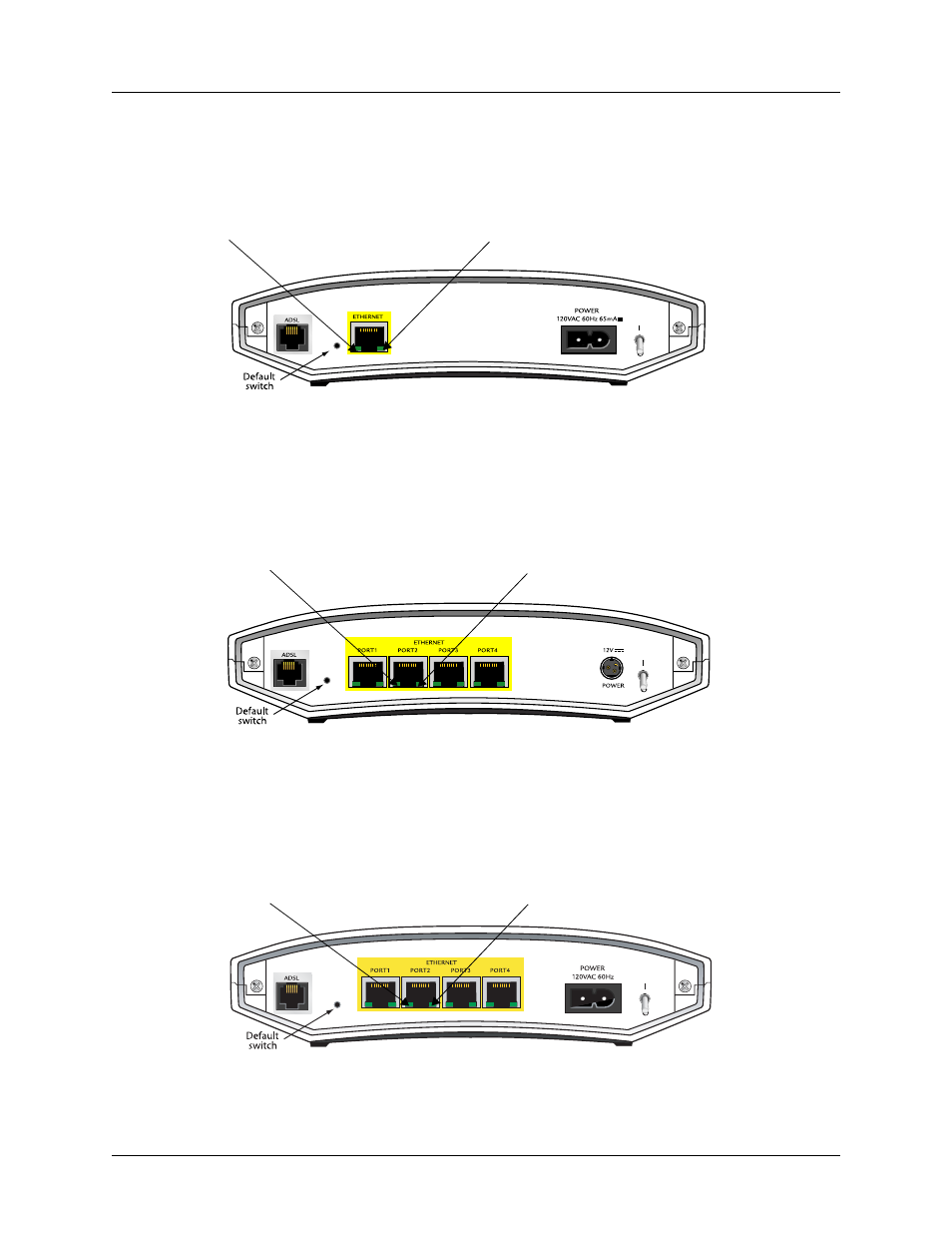
Reviewing the Rear Panel Design
Figure 2 shows the NetVanta 340 rear panel. The activity and link LEDs, which are present on all NetVanta
Ethernet ports, are labeled. The NetVanta 340 accommodates a 120 VAC power supply.
Figure 2. NetVanta 340 Rear Panel Layout
Figure 3 shows the NetVanta 344 rear panel. Note that the NetVanta 344 has four Ethernet ports, each with
its own activity and link LEDs. Note that the activity and link LEDs on the NetVanta 344 are reversed from
the NetVanta 340. The NetVanta 344 accommodates a 12 VDC power supply.
Figure 3. NetVanta 344 Rear Panel Layout
Figure 4 shows the NetVanta 347 rear panel. Note that the 347 has four Ethernet ports, each with its own
activity and link LEDs. Also note that the activity and link LEDs are reversed from the NetVanta 340 but
the same as the NetVanta 344. The NetVanta 347 accommodates a 120 VAC power supply.
Figure 4. NetVanta 347 Rear Panel Layout
Link LED (green)
Activity LED (amber)
Activity LED (amber)
Link LED (green)
Activity LED (amber)
Link LED (green)