Midi implementation chart – elektraLite CP1 User Manual
Page 18
product manual
model nº c p 1
# E_10051a
Elektralite
display. If the “received” message does not appear, then the memory dump was improperly received. The CP-1 must not
be in enter scene, chase or macro mode when receiving a memory dump. The contents of the memory messages are
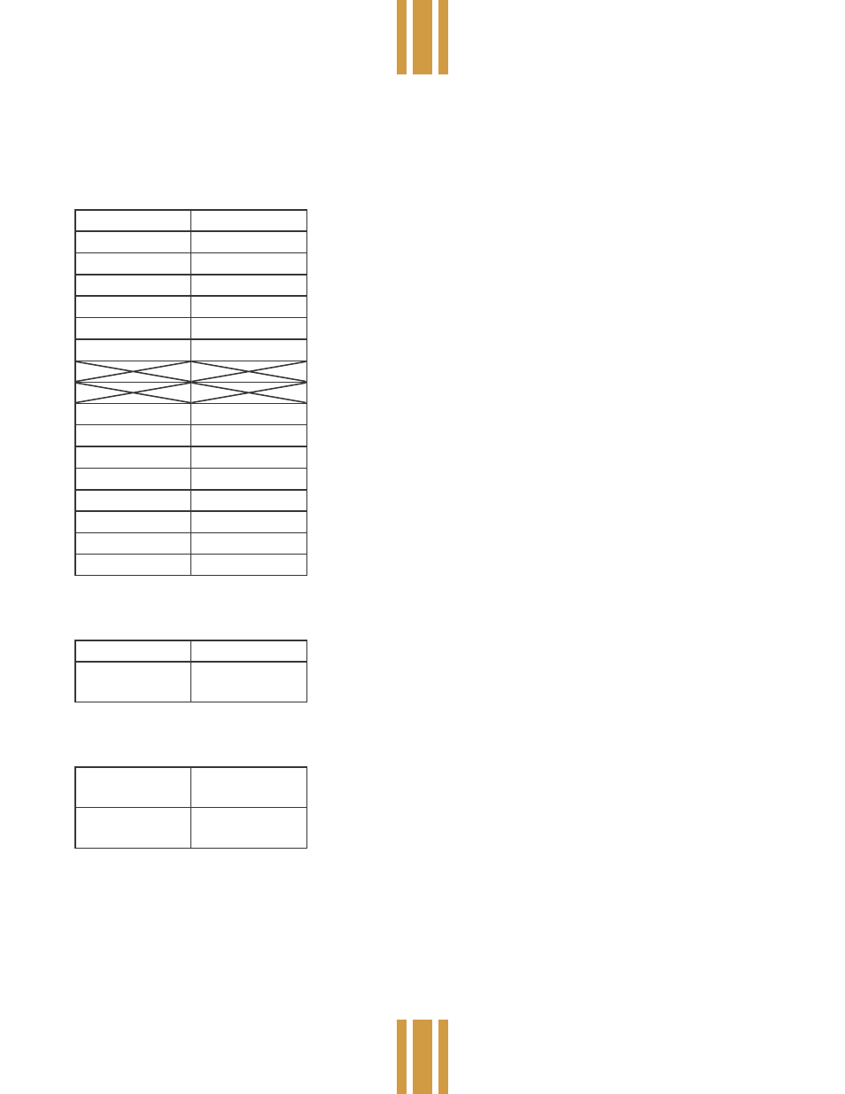
shown in the MIDI implementation chart which follows.
MIDI Implementation Chart
NOTE: All numbers are in hexadecimal unless stated otherwise. Continuous Controllers (sent and received)
Bn 00 bb
Bank select
Bn 01 vv
Inst. 1 Iris
Bn 02 vv
Inst. 1 Color
Bn 03 vv
Inst. 1 Gobos
Bn 04 vv
Inst. 1 Strobe
Bn 05 vv
Inst. 1 Pan
Bn 06 vv
Inst. 1 Tilt
Bn 2B vv
Inst. 8 Iris
Bn 2C vv
Inst. 8 Color
Bn 2D vv
Inst. 8 Gobos
Bn 2E vv
Inst. 8 Strobe
Bn 2F vv
Inst. 8 Pan
Bn 30 vv
Inst. 8 Tilt
Bn 31 vv
Xfade Speed
Bn 32 vv
Chase Speed
n = MIDI channel (0-F), bb = bank (0-3), w = 7 bit value (0-7F)
Program Changes (sent and received)
Cn 00
Blackout
Cn vv
Scenes, Chases
and Macros
Note: scenes, chases and macros are always preceded by a bank select message.
System Exclusive Messages
F0 00 00 19 05
01 dd ... F7
Memory dump
F0 00 00 19 05
00 F7
Memory dump
request
dd = 61,000(dec.) data bytes