Spektrum SPMAR12120 User Manual
Page 16
EN
16
5. Have your helper position the model in various orientations (nose up, nose
down, nose toward the Tx, nose away from the Tx, etc.) while your helper
watches the Flight Log noting any correlation between the aircraft’s orientation
and frame losses. Do this for 1 minute. The timer on the transmitter can be used
here. For giant-scale aircraft, it’s recommended that the airplane be tipped up
on its nose and rotated 360 degrees for one minute then the data recorded. Next
place the airplane on its wheels and do a second test, rotating the aircraft in all
directions for one minute.
6. After one minute, a successful range check will have less than ten recorded
frame losses. Scrolling the Flight Log through the antenna fades (A, B, L, R)
allows you to evaluate the performance of each receiver. Antenna fades should
be relatively uniform. If a specific antenna is experiencing a high degree of fades
then that antenna should be moved to a different location.
7. A successful advanced test will yield the following:
H - 0 holds
F - less than 10 frame losses
A, B, R, L - Frame losses will typically be less than 100. It’s important to
compare the relative frame losses. If a particular receiver has a significantly
higher frame loss value (2 to 3X) then the test should be redone. If the same
results occur, move the offending receiver to a different location.
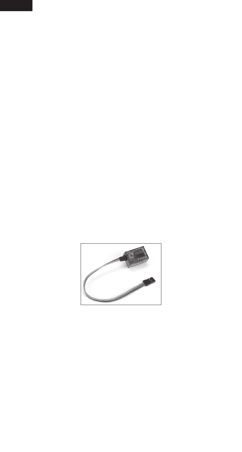
Flight Log
The Spektrum Flight Log (SPM9540) is compatible with the AR12120 PowerSafe.
The Flight Log displays overall RF link performance as well as the individual
internal and external receiver link data. Additionally it displays receiver voltage.
Using the Flight Log
After a flight and before turning off the receiver or transmitter, plug the Flight Log
into the Data port on the PowerSafe. The screen will automatically display voltage
e.g. 6v2= 6.2 volts.
When the voltage reaches 4.8 volts or less, the screen will flash
indicating low voltage.
Press the button to display the following information:
A - Antenna fades on antenna A
B - Antenna fades on antenna B
L - Antenna fades on the left antenna
R - Antenna fades on the right antenna
F - Frame loss
H - Holds