Dx2 with digital spectrum modulation, Binding, Dx2 with digital spectrum modulation binding – Spektrum SPM2020 DX2 User Manual
Page 6
6
The DSM system operates in the 2.4GHz band (that’s 2400MHz). This high frequency offers
a significant advantage as it’s well out of the range of model-generated radio interference
(like motor and ESC noise). All the complex issues that now exist using 27 and 75MHz
radios with model-generated interfering noise are eliminated with this system. The DSM
system uses Direct Sequencing Spread Spectrum modulation to generate a wide signal on a
single frequency. The FCC requires that these systems be “smart”– incorporating collision
avoidance such that when a system is turned on, it scans the 2.4GHz band and selects a
channel that is not being used, then begins transmitting on that unused channel. 79 channels
are available and the odds of one DSS spread spectrum system interfering with another are
astronomically remote. The 2.4GHz spectrum has a capacity of 79 channels. In the unlikely
event that the spectrum is full, the 80th system will not connect or cause any interference
going into hold scan until a channel is free.
DX2 with
Digital
Spectrum
Modulation
During the first installation, the receiver(s) must be bound to the transmitter. Binding is
necessary to program the receiver(s) to distinguish its corresponding transmitter from
others. Also fail-safe positions are transferred from the transmitter to the receiver during
binding. See binding below for more details.
It is necessary to bind the receiver to the transmitter during the first installation, and is
recommended when the receiver is moved from one vehicle to another. Receivers can be
re-bound to the same transmitter or to other transmitters an infinite number of times. Also
multiple receivers can be bound to a single transmitter, common when using one transmitter
to operate several models.
Only bound receivers and transmitters can connect. During power-up, the transmitter scans
for a free channel while the receiver scans for its bound transmitter. During the scanning
process LEDs on both transmitter and receiver flash rapidly. When control is achieved the
LED remains on continuously.
In the unlikely event that the link is lost during use, the receiver will drive the servos to
their fail-safe positions that were preset during the binding process. If the receiver is turned
on prior to turning on the transmitter, the receiver will enter the fail-safe mode, driving the
servos to their preset fail-safe position. When the transmitter is turned on, normal control is
resumed.
To bind the receiver to the transmitter
1. Make sure the transmitter and receiver are turned off
������
���
���
��
���
�������
�������������
����������������
�������������������������
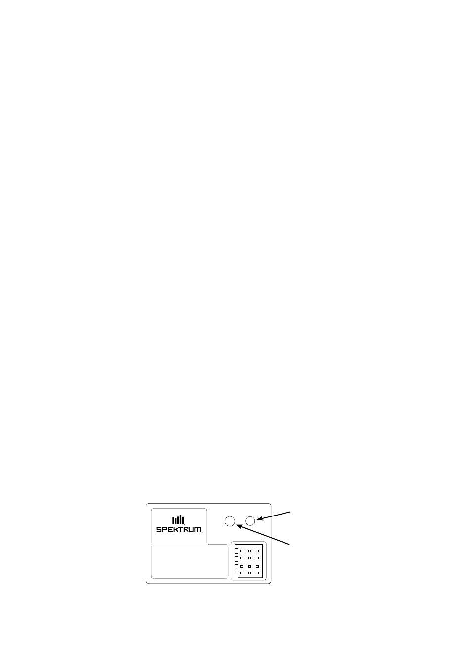
2. With the receiver off, press and hold the bind button on the receiver while turning on
the receiver.
3. Release the bind button when the LED flashes green.
Binding
Bind Button
LED