Installation of the cooling components, Mcr120-f, Adiator installation – Swiftech H20 120 R2 User Manual
Page 7: Mcp650, Ump installation, Ater, Block, Nstallation, Mcres-525, Reservoir installation
II.
Installation of the cooling components
The following is a typical sequence of components installation. Placement of the cooling components may vary depending on your chassis and
motherboard configurations. A mock-up installation is thus necessary to estimate the length of the different sections of tubing that will be required
between each component.
1.
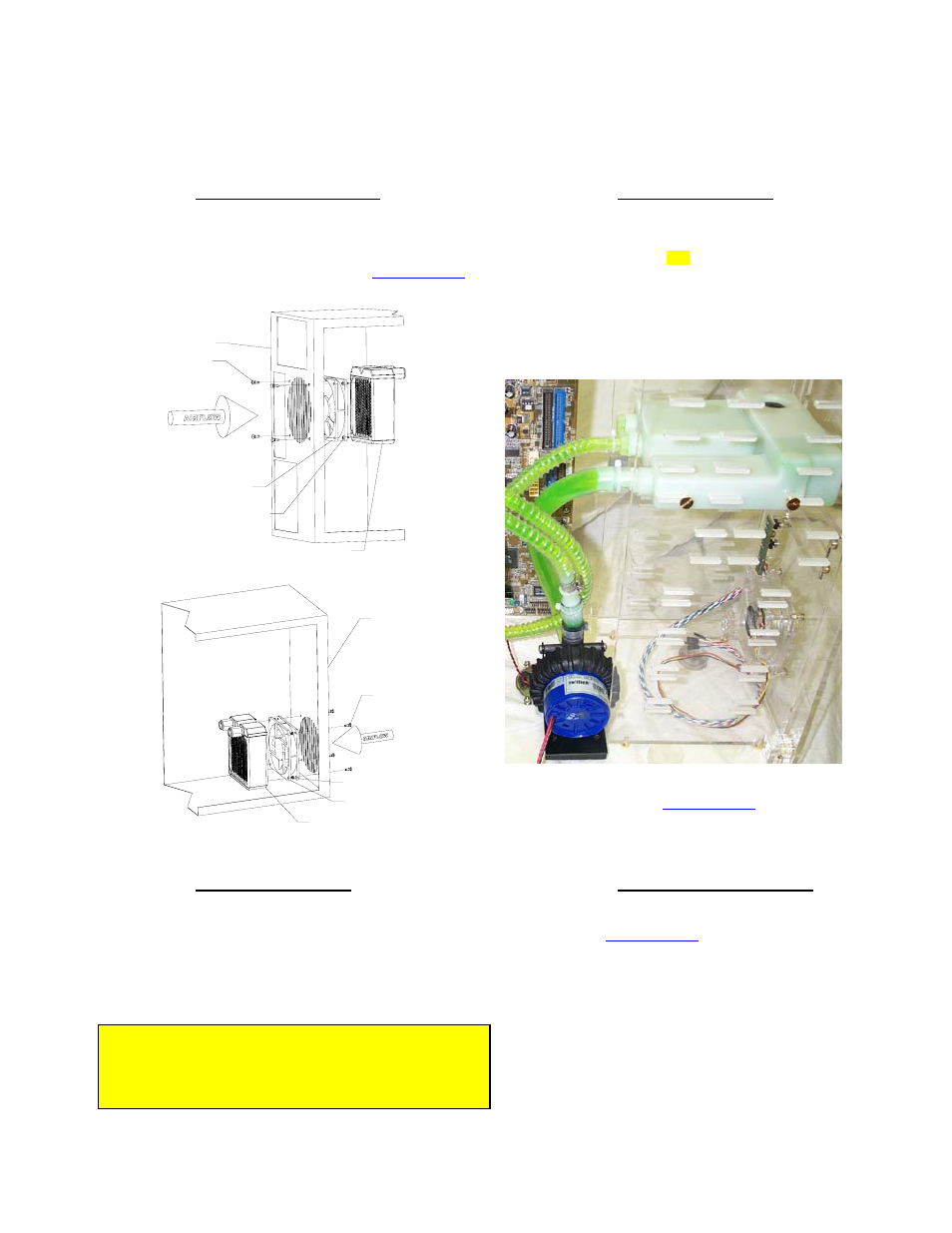
MCR120-F Radiator installation
The radiator/fan assembly fits into any exhaust opening designed to
receive a 120mm case fan. Depending on the case design, the radiator
can be installed in the back of the case (most common) as shown fig 1,
or the front of the case. Please refer to the separate
provided in appendix to fasten the radiator to the chassis.
Back
of
Chassis
Snap-rivet
120mm fan
MCR120 Radiator
6-32 x 3/8" philips
Figure 1
Front
of
Chassis
Snap-rivet
6-32 x 3/8" philips
MCR120 radiator
120mm fan
Figure 2
2.
MCP650 Pump installation
Preferable position is at the bottom of the chassis. However, the
pump can operate in any position. For optimum safety, the pump
can be bolted to the chassis. TIP! Do not peel-off the protective
sticker until you are satisfied with the position of the pump, as
subsequent removal is destructive to the foam gasket.
The pump’s inlet and outlet are ½” in outside diameter. A
1½ ft.
length of ½” ID tubing is pre-installed on the pump inlet and will be
connected directly to the reservoir ½” barb discharge. The pump
discharge is pre-installed with a 3/8” barb adapter and connects to
the rest of the circuit.
Figure 3
Please refer to the separate
for specific information regarding the installation of the pump.
3. Water-block(s)
Installation
When provided in kit form, the MCW6000 series water-blocks
receive 2 ft. of pre-installed tubing at the inlet and outlet. In dual
processor kits, one of the water-blocks inlets is free of tubing so that
water-blocks may be installed in series.
Please refer to your specific model installation guide provided in
appendix to install your water-block to the motherboard.
4.
MCRES-525 reservoir installation
Install the MCRES-525 reservoir in the desired 5 ¼” bay,
following the
located in appendix.
Uppermost drive bay is preferred, but not mandatory.
Remember when you fill-up the system that your circuit will
respond to the laws of communicating vases. If the radiator
for example is higher than the reservoir, you will want to hold
the reservoir higher than the radiator while filling it up so that
it doesn’t overflow, then close the fill-cap, then secure the
radiator in the desired bay.
Position the reservoir so that it protrudes approximately 1 ½”
outside of the case. Measuring the length of tube needed in
this position will give sufficient slack in the line so that you
can pull the reservoir enough to fill-it-up during maintenance
operations.
TIP!
For the mock-up installation, interposing a piece of
paper between the water-block and the processor will protect
both the cooler and the processor surfaces.
Rouchon Industries, Inc., dbA Swiftech™ – 1703 E. 28
th
St, signal Hill, CA 90755, USA – T (562) 595-8009 – F (562) 595-8769 – All content
Copyright Swiftech 2004 – Last edited 9-27-04 – Subject to revision without notice
- 7 of 40 -