Swiftech MCW5002 PT User Manual
Page 4
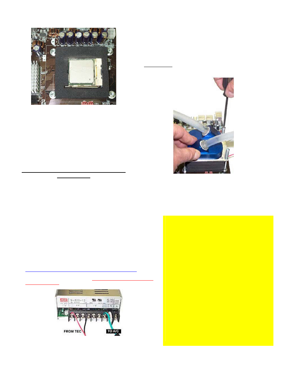
Figure 8
Remove the peel-off paper back from the
motherboard gasket, and install it as shown above.
The sticky side should be towards the motherboard.
Insert the processor into the socket. Since you
have grease inside the socket, some hydraulic
pressure lift may occur: for this reason, make sure
that the processor sits perfectly flat, and is inserted
all the way into the socket.
Then, drop a small amount of high quality thermal
compound onto the center of the processor core.
Installation of the cooler to the motherboard is
now complete!
Securing the MCW5002-PT cooler to the motherboard:
Install the MCW5002-PT
assembly onto your processor, as shown in
figure 9.
Gradually tighten the screws in a crisscross pattern until you feel that they
reach the bottom of the standoff. A “finger-tight” lock is sufficient.
Conversely, adjustments such as tightening the screws only partially are
strictly prohibited. Such attempts will result in improper contact between the
CPU core and the heat sink, and result in CPU overheating.
Figure 9
(showing an MCW5000-PT)
c. Electrical
Installation
IMPORTANT WARNING: Solder joints of the wires to the thermoelectric module are extremely fragile. Bending the wires at their root will break the
solder joint, with no possible repair. Swiftech will not honor the warranty for broken wires.
a. Recommended installation: Connecting to a dedicated auxiliary
power supply
Minimum requirements for a dedicated power supply are 25A @ +12V.
Your TEC module has been measured to draw 18 amps at 12 volts. For this
reason, we recommend using the “Meanwell S320-12” auxiliary power supply,
available on our website in the Thermoelectric accessories section.
The TEC module is provided with “bare wires” to facilitate installation with screw
type terminals such as featured in the S320-12 power supply
Connect red wire from TEC module to the +V terminal, and black wire to the –V
terminal as shown in figure 10.
A complete installation guide for the S320-12 power supply kit is available here:
includes a wiring harness and a relay switch to synchronize the power to the
S320-12 with your computer, which is a
highly recommended (read critical
recommendations)
Figure 10
C
C
R
R
I
I
T
T
I
I
C
C
A
A
L
L
R
R
E
E
C
C
O
O
M
M
M
M
E
E
N
N
D
D
A
A
T
T
I
I
O
O
N
N
S
S
M
M
U
U
S
S
T
T
R
R
E
E
A
A
D
D
!
!
!
!
!
!
Never run a thermoelectric module without coolant flowing
in the circuit. This will result in catastrophic failure of the
cooling element, and may cause any/all of the following:
Tubing to burst open due to coolant overheating
Permanent failure of the Peltier module
Permanent damage to the CPU and/or motherboard
due to excess heat
It is highly recommended to dedicate the auxiliary power
supply for the thermoelectric module to the computer
power-supply, so that the Peltier module will never run by
itself without cooling fluid.
For this purpose, we recommend using the following
accessory, available in our online shopping cart: PRS Kit II.
Includes: Relay Switch Circuit board AC socket, S/S socket
cover, power cord.
This relay switch is rated for
110 to
220~240 volts and up to 50A inrush
current. It is suitable for
use with the S-320-12 Meanwell power supply recommended
above.
If you run your computer unattended for extended periods
of time, it is also a good practice to setup an alarm
temperature, which will shut down the computer in case the
CPU overheats. Such alarm/shut down process should be
tested as functional.
Page 4 of 5 - Created 7-10-04 - Copyright
Swiftech – All rights reserved – Subject to change without notice