Swiftech MCW462TEC INTEL User Manual
Page 2
Copyright Swiftech 2001 – All rights reserved – Last revision date: Feb 1, 2002
Rouchon Industries, Inc., dbA Swiftech – 1703 E. 28
th
Street, Signal Hill, CA 90806 – Tel. 562-595-8009 – Fax 562-595-8769
E Mail: Swiftech @swiftnets.com – URL:
http://www.swiftnets.com
Information subject to change without notice
Page 2
•
To further prevent condensation to occur behind the motherboard, a neoprene sticker is provided with your water-block accessories.
Apply it to the back of the motherboard, behind the processor.
•
Re-install the MB inside the case.
II. Water-block installation
•
IMPORTANT WARNING: the solder joints to
the wires of the thermoelectric module are
extremely fragile. Bending the wires at their
root will systematically break the solder joint,
and the thermoelectric module cannot be
repaired. For this reason, we route the wires
inside the holes of the brackets that are
normally used to mount socket 423 or Xeon
processors. If you need to use these mounting
holes for your Xeon or socket 423 Pentium 4,
you should first disassemble the brackets, very
carefully re-route the wires in the socket 478
mounting holes, then re-install the brackets.
Swiftech will not honor the warranty for broken
wires.
•
It is preferable to insert the tubing into your
MCW478-UT water-block prior to installing it
onto the CPU. The reason is that inserting the
tubes into the fittings requires some strength,
and it is preferable not to do this while the block
is sitting on the CPU. If you are going to use
soft vinyl tubing (transparent tubing), it is
IMPERATIVE that you use the two plastic
inserts provided with your kit.
•
Orientation of the block is important for
bleeding purposes. Please look-up the
critical bleeding instructions paragraph on
page 3 prior to installing the block onto the
CPU.
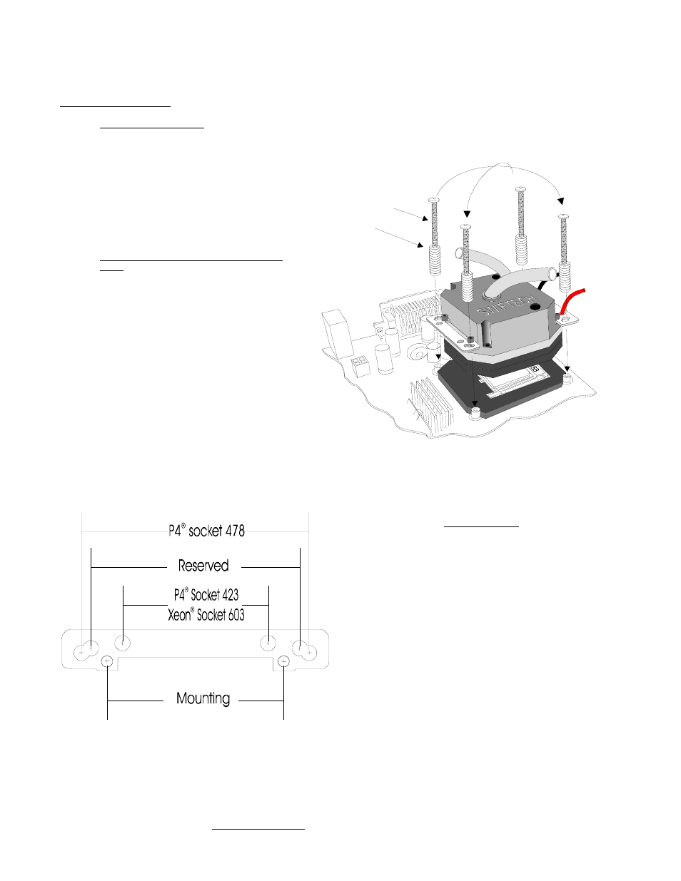
2“ screw
Spring
Crisscros
tightening
pattern
Figure 3
•
Identify the mounting holes on the bracket for your
particular processor, as shown in the schematic
below:
2"
2"
2"
2"
Install the water-bl;ock assembly onto your processor, as shown
on figure 3. Gradually tighten the screws in a crisscross pattern
until you feel that they reach the bottom of the standoff. A “finger-
tight” lock is sufficient. Over tightening may result in stripping the
nylon hex nut. Conversely, adjustments such as tightening the
screws only partially are strictly prohibited. Such attempts will result
in improper contact between the CPU core and the heat sink, and
result in CPU overheating.
Due to wide variations in gasket thickness tolerances, we
suggest that you uninstall the water-block once, following the
initial assembly just to verify that you have good contact
between the cold plate and the CPU. Inspect the grease imprint
that the CPU left on the copper plate: it should be perfectly
even!