Swiftech MCW462TEC User Manual
Parts list
Copyright Swiftech 2001 – All rights reserved – Last revision date: Feb 1, 2002
Rouchon Industries, Inc., dbA Swiftech – 1703 E. 28
th
Street, Signal Hill, CA 90806 – Tel. 562-595-8009 – Fax 562-595-8769
E Mail: Swiftech @swiftnets.com – URL:
http://www.swiftnets.com
Information subject to change without notice
Page 1
Parts list
Parts
AMD
INTEL
QTY
PARTS
AMD
INTEL
QTY
Water-block, with TEC & gaskets assy.
X
1
Nylon 6-32 Hex nuts
Common to both
4
6-32 x 2” screws (for WB)
Common to both
4
Black fiber washers
X
4
Standoffs
Common to both
4
Thermal grease
Common to both
1
Springs
Common to both
4
Tube insert
Common to both
2
.230x.096 Nylon spacers
X
4
Pentium 4 brackets
X
2
.220x.046 Nylon spacers
X
4
4-40 socket screws
X
4
AMD motherboard gasket
X
1
Preamble:
This product is intended for expert users only. Please consult with a qualified technician for installation. Improper installation may result in
damage to your components.
Swiftech assumes no liability whatsoever, expressed or implied, for the use of these
products, nor their installation.
The following instructions are subject to change without notice. Please visit our web site at
www.swiftnets.com
for updates.
I. Preparing the motherboard
You must uninstall your MB prior to installing the MCW462-UT water-block.
•
Install standoffs in MB
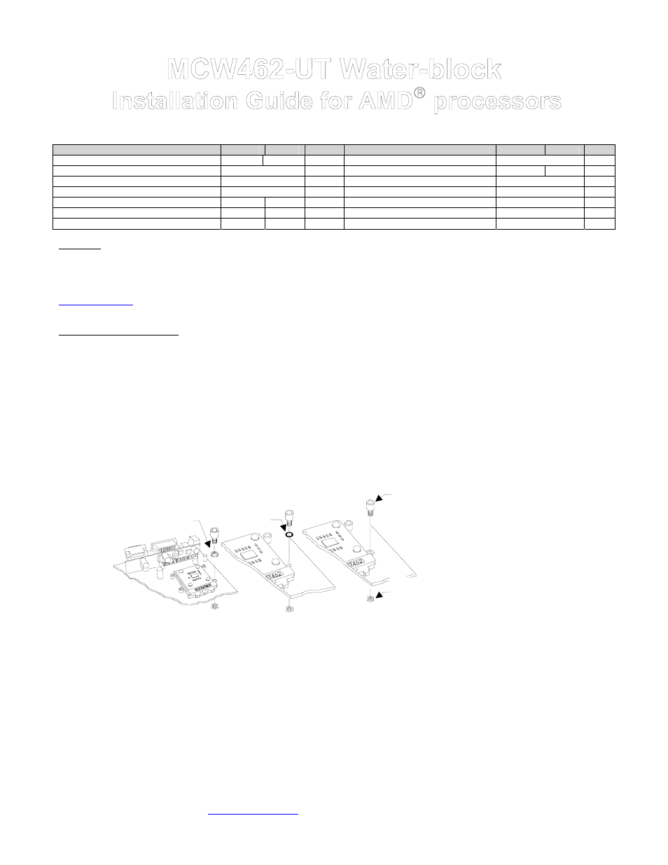
Determine which standoff washers to use, depending on your MB mounting holes:
o
Large holes .230”(5.8mm) diameter : use .220x.046 Nylon spacers. The washers fit inside the MB hole.
o
Small grounded holes .150”(3.8mm) diameter: you can recognize grounding by a silver ring around the holes; no washers
needed nor necessary.
o
Small holes, NOT grounded (bare circuit board): you must use black fiber washers, or damage to the MB may occur.
MB with
large holes
MB with
small holes,
NOT grounded
MB with
small holes,
grounded
Use .220x.046
nylon spacer
(fit inside the hole)
Use black
Fiber washer
No washer
necessary
Standoff
Nylon, hex nut
on back side of
the MB
Figure 1
Install standoff in each one of the
four holes surrounding the socket.
Keep the standoff & washer
centered over the MB holes, and
secure with nylon hex nuts on
backside of the MB. If you are
going to assemble/disassemble the
heat sink frequently, we
recommend finishing the installation
by putting a drop of “Crazy Glue “ at
the junction between standoff & MB,
and between nylon hex nut & MB.
This will lock the standoff onto the
MB, and further prevent it from
spinning lose during frequent
assembly and disassembly
operations.
•
Fill-up the socket with dielectric grease. Do not confuse dielectric grease with thermal compound. Dielectric grease is used to
prevent condensation where parts are exposed to cold. We recommend Luberex (available on our web site under the accessories
section), or any similar product, with good dielectric properties. Fill-up the socket center cavity (grease is to be level with the upper
surface of the socket), and coat the socket pinholes with grease. Spread the grease with your finger so that it will penetrate inside
the pinholes.
•
Insert the processor into the socket. Since you have grease inside the socket, some hydraulic pressure lift may occur: for this
reason, make sure that the processor sits perfectly flat, and is inserted all the way into the socket. Then, lightly coat the processor
core with high quality thermal compound. Only a paper-thin coat is necessary. It should be applied using preferably a razor blade,
or a credit card, held between thumb and index at a 45-degree angle. It is critical to ascertain that the entire core is covered with a
uniform coat of thermal compound. Thermal performance will dramatically decrease if any portion of the core is not covered by
thermal compound. We recommend Arctic Silver or similar high-end compound for superior thermal conductivity.