Swiftech MCX462 User Manual
Page 2
Copyright Swiftech 2001 – All rights reserved – Last revision date: Oct. 2001
Rouchon Industries, Inc., dba Swiftech – 1703 E. 28
th
Street, Signal Hill, CA 90806 – Tel. 562-595-8009 – Fax 562-595-8769
E Mail: Swiftech @swiftnets.com – URL:
http://www.swiftnets.com
Information subject to change without notice
Page 2
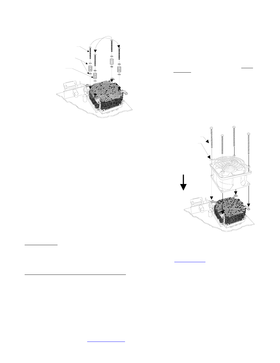
6-32 x 1 ½“
Philips screw
.230x.096
Nylon spacers
Spring
Crisscros
tightening
pattern
4.
Prepare 4 assemblies composed of (1) 1 ½”
screw, (2) .230x.096 Nylon spacers, and (1)
spring as shown in the picture to the left. Drop
each assembly in the heat sink mounting holes.
While gently pressing at the center of the heat
sink, start tightening the screws gradually in a
crisscross pattern until you feel that they reach the
bottom of the standoff. A “finger-tight” lock is
sufficient. Over tightening may result in stripping
the nylon hex nut. Conversely, adjustments such
as tightening the screws only partially are strictly
prohibited. Such attempts will result in improper
contact between the CPU core and the heat sink,
and result in CPU overheating.
5.
Fan Installation: Place the fan over the heat sink. The airflow
should be blowing down (fan label facing down). Place the fan guard
over the fan. Tighten the four 6-32 x 2” screws. The fan is equipped
with two connectors: a four pin molex connector which must be
connected to the power supply, and a 3 pin single wire connector
which connects to the MB fan sensor header.
6.
Optional fan rheostat: a rheostat model # RH070 is sold
separately, and allows to adjust the fan speed. It connects between
the fan power connector and the power supply connector. Please
consult your distributor if you wish to purchase this item. Reducing
the fan speed reduces fan noise up to 9 dBA. It also reduces
thermal performance, and will affect overclocking performance
accordingly. It is however perfectly appropriate for non overclocked
processors.
6-32 x 2“
Philips screw
Fan guard
Direction of
the flow
(fan label
facing down)
III. Final inspection
Now that the heat sink is installed, startup your computer, go into the BIOS and observe the CPU temperature. Under normal ambient
temperature conditions, the processor temperature should never exceed 55
°
C (130
°
F). If it does, shut down the computer immediately,
and review your entire installation. Troubleshooting help is available on our web site at
www.swiftnets.com
, or by calling customer
support at 562-595-8009.
Uninstall note: CPU removal from some socket motherboards
Once in place, the standoffs may slightly interfere with CPU removal in some motherboards:
Depending on the manufacturers, sockets use either a plastic locking arm, or a metal locking arm. Sockets using a plastic locking arm require
that the arm be slightly pried open at the center in order to release it from its retaining tab. This can easily be done by inserting a thin
screwdriver in between the socket body and the arm’s mid-section, and by slightly twisting the screwdriver in either direction, while pulling on
the arm. This will slightly arch the mid-section of the arm, and release it from its locking tab.
DISCLAIMER: Swiftech assumes no liability whatsoever, expressed or implied, for the use of these products.