Pinout assignments – Allied Telesis AT-FS202SC/FS4 User Manual
Page 30
20
Table 10 Fiber Optic Loss Specification (Benchmark)
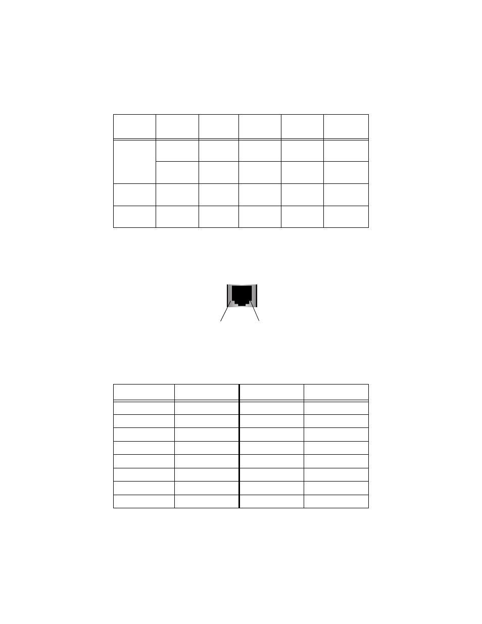
Pinout Assignments
Figure 1 shows the pin assignments of the RJ-45 connector.
Figure 1 RJ-45 Pin Assignments
Table 5 lists the 10/100Base-TX connector pins and their signals when the port
is operating in either MDI or MDI-X configuration.
Table 11 RJ-45 Pinouts
Fiber Type
1
1. MMF = Multimode Fiber / SMF = Single-mode Fiber.
Fiber Optic
Diameter
Optical
Frequency
Typical Loss
Factor
Worst Case
Loss Factor
Bandwidth
MMF
50/125
microns
1310 nm
1.00 dB/km
1.50 dB/km
400 Mhz-km
62.5/125
microns
1310 nm
1.00 dB/km
1.50 dB/km
500 Mhz-km
SMF
9/125
microns
1310 nm
0.40 dB/km
1.00 dB/km
Not
applicable
SMF
9/125
1550 nm
0.30 dB/km
0.75 dB/km
Not
applicable
MDI-X (Default)
Signal
MDI
Signal
1
RX+
1
TX+
2
RX-
2
TX-
3
TX+
3
RX+
4
-
4
-
5
-
5
-
6
TX-
6
RX-
7
-
7
-
8
-
8
-
Pin 1
Pin 8