Transmitter, Fiber optic port specifications – Allied Telesis AT-FS202SC/FS4 User Manual
Page 28
18
Immunity
Conforms to EN55024 immunity standard
EMI/RFI
Meets all applicable requirements for emissions
including but not limited to FCC Class A, IC
Class A, EN55022 Class A
Transmitter
Output Power
62.5/125 mM
-16.8 dBm
100/140 mM
50/125 mM
-20.3 dBm
85/125 mM
Fiber Optic Port Specifications
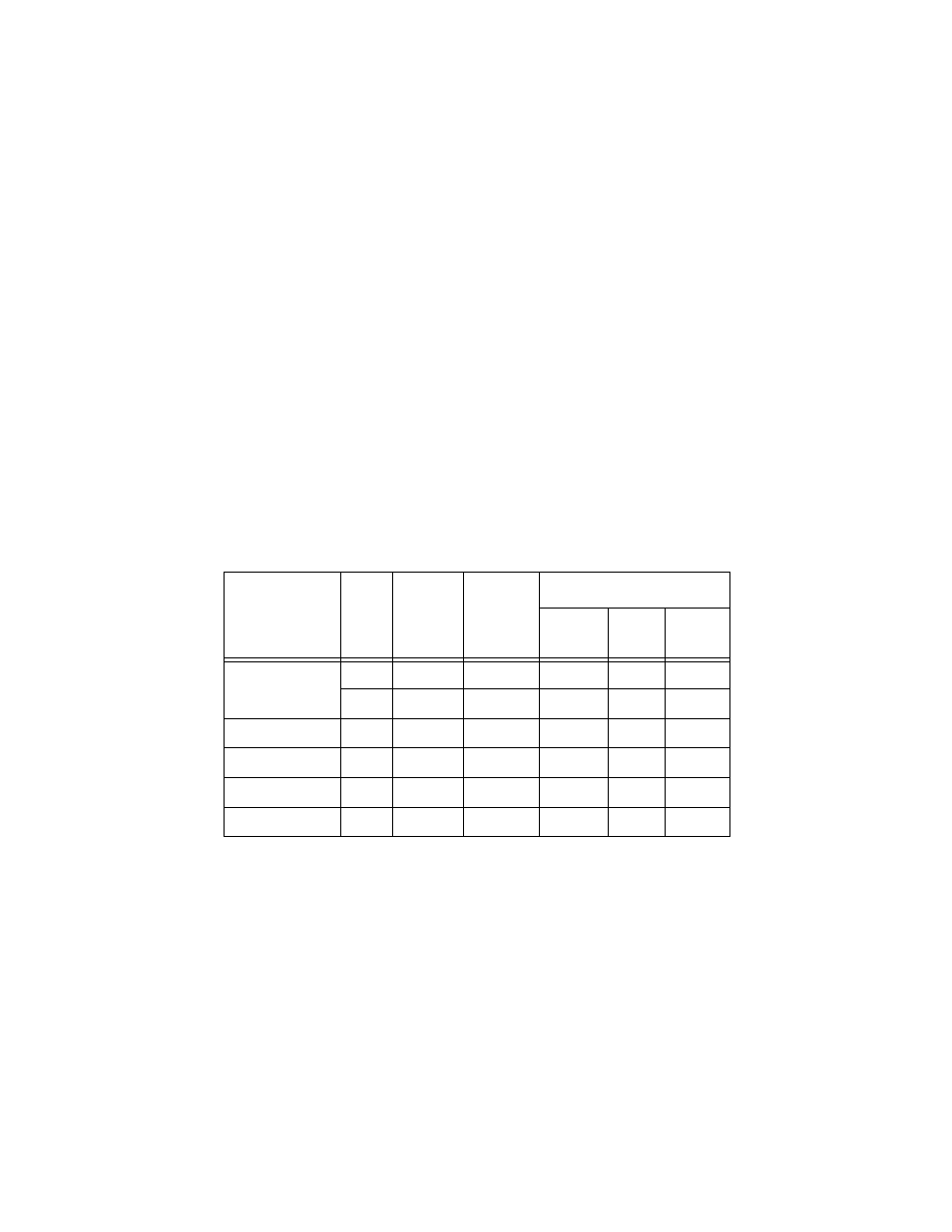
Table 7 through Table 10 lists the specifications for the fiber optic port.
Table 7 Fiber Optic Transmitter
Model
Fiber
Type
1
1. MMF = Multimode Fiber / SMF = Single-mode Fiber.
Fiber
Optic
Diameter
(microns)
Optical
Frequency
Launch Power (dBm)
2
2. The launch power is measured at one meter from the transmitter.
Max.
Avg.
Min.
AT-FS201 &
AT-FS202
MMF
50/125
1310 nm
-14.0
-20.3
-22.5
MMF
62.5/125
1310 nm
-14.0
-16.8
-19.0
AT-FS202SC/FS1
SMF
9/125
1310 nm
-8.0
-11.5
-15.0
AT-FS202SC/FS2
SMF
9/125
1310 nm
0.0
-3.0
-5.0
AT-FS202SC/FS3
SMF
9/125
1310 nm
0.0
-2.0
-4.0
AT-FS202SC/FS4
SMF
9/125
1550 nm
0.0
-1.5
-3.0