Network topologies – Allied Telesis AT-FS202SC/FS4 User Manual
Page 18
Description
8
Network Topologies
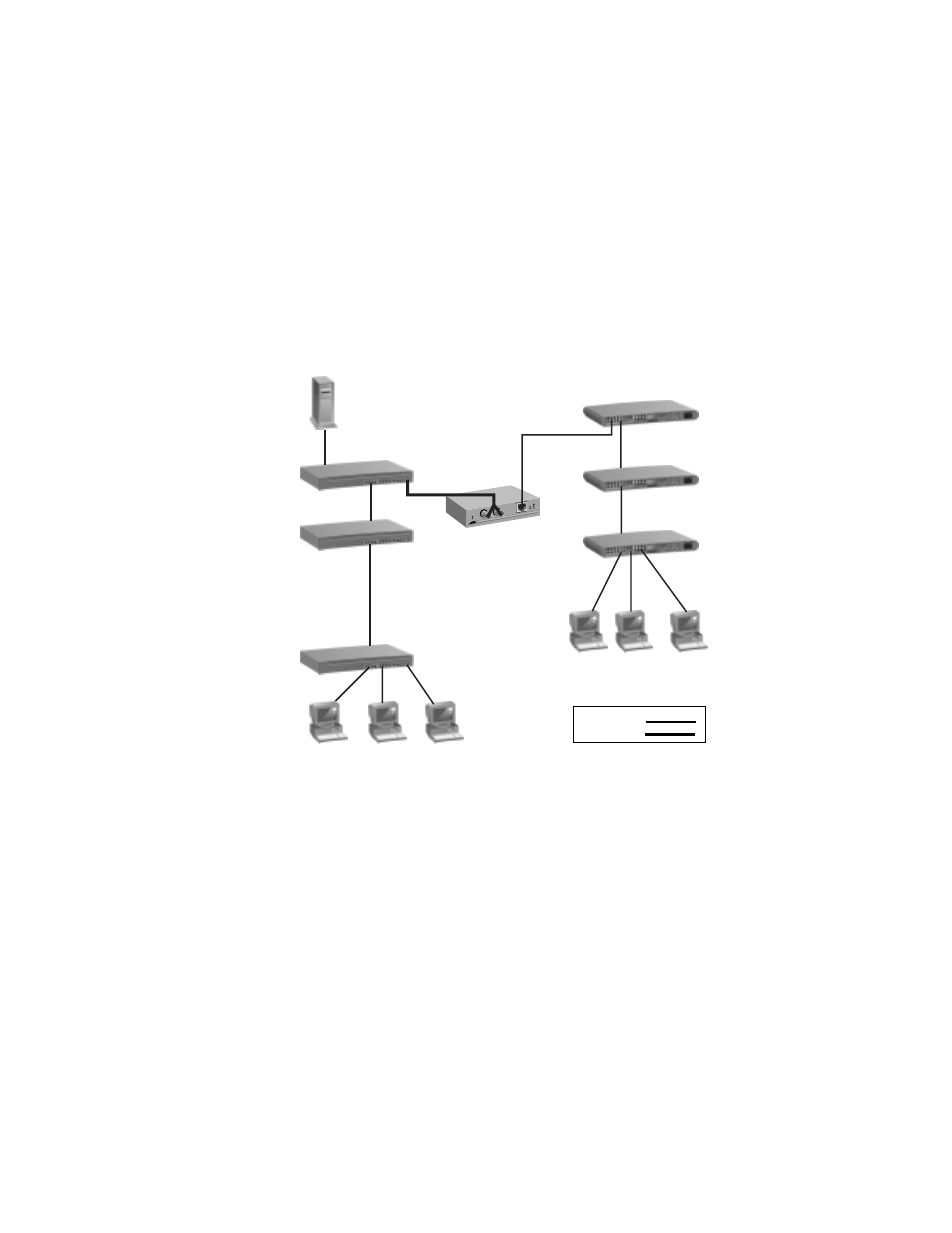
Figure 4 illustrates a topology using one AT-FS201 switch to interconnect two
small networks of stackable hubs. Network 1 has an AT-FH812u with an
AT-FH807u switching module connected to the 100Base-FX port on the
AT-FS201. Network 2 has an AT-3624TR hub connected to the 10/100Base-TX
port on the AT-FS201.
Figure 4 Network Topology
Network 1
AT-FH812u
with an
AT-FH807u
module
AT-FH812u
AT-FH812u
AT-FS201
AT-3624TR
AT-3624TR
AT-3624TR
Network 2
Twisted Pair
Fiber Optic
This manual is related to the following products: