Allied Telesis AT-FS202SC/FS4 User Manual
Page 21
AT-FS20x and AT-FS202SC/FSx Series Installation Guide
11
Note
Refer to “Fiber Optic Port Specifications” on page 18 for additional
information on the fiber optic port.
❑
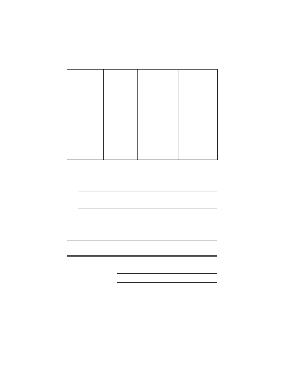
Refer to Table 5 for the cabling specifications for the fiber optic port
operating in half-duplex mode.
AT-FS202SC/FS1
50/125 or 62.5/
125 multimode
2 km (1.2 mi)
13 dB at 1310 nm
9/125 micron
single-mode
15 km (9.3 mi)
16 dB at 1310 nm
AT-FS202SC/FS2
9/125 micron
single-mode
40 km (24.8 mi)
30 dB at 1310 nm
AT-FS202SC/FS3
9/125 micron
single-mode
75 km (46.5 mi)
33 dB at 1310 nm
AT-FS202SC/FS4
2
9/125 micron
single-mode
100 km (62 mi)
34 dB at 1550 nm
1. Maximum distance for 100 Mbps optical datalinks is dependent on the following factors: type of optical fiber,
duplex mode of both end-nodes, and maximum optical loss budget for each of the optical fiber at the operating
optical wavelength.
2. The cable must be non-dispersion-shifted, dispersion-shifted, or non-zero dispersion-shifted single-mode fiber
optic cable.
Table 5 100Base-FX Fiber Optic Ports (Half-duplex)
1
Number of Media
Converters
Connected Devices
Maximum Operating
Distance
One Media Converter Inline
Switch to switch
372 m (1,221 ft)
Workstation to switch
372 m (1,221 ft)
Switch to Class I repeater
137 m (450 ft)
Switch to Class II repeater
185 m (607 ft)
Table 4 100Base-FX Fiber Optic Cabling Specifications (Full-duplex) - continued
Model
Fiber Optic
Cable
Maximum Operating
Distance
1
Maximum
Allowable Loss
Budget