Chapter 1: installation 24 – Allied Telesis AT-MCF2000S User Manual
Page 24
Chapter 1: Installation
24
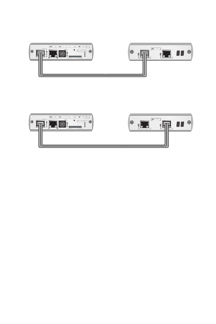
Figure 7. Connecting the Management and Stacking Modules
2.
To cable two stacking modules, connect the STACK 1 or
STACK 2 port on one stacking module to either the STACK 1
or STACK 2 port on another stacking module.
All port combinations are supported. See Figure 8 on page
25.
AT-MCF2000S
LINK
ACT
PORT ACTIVITY
STACK 1
STACK 2
AT-MCF2000S
LINK
ACT
PORT ACTIVITY
STACK 1
STACK 2
AT-MCF2000M
STACK
MANAGEMENT
TERMINAL
10/100/1000BASE-T
RS-232
RESET
SD
RDY
BUSY
MASTER
POWER
BOOT
RDY
FAULT
1000 LINK
ACT
10/100 LINK
ACT
FDX
HDX
COL
LINK
ACT
PORT ACTIVITY
SYSTEM
0
31
ID
AT-MCF2000M
STACK
MANAGEMENT
TERMINAL
10/100/1000BASE-T
RS-232
RESET
SD
RDY
BUSY
MASTER
POWER
BOOT
RDY
FAULT
1000 LINK
ACT
10/100 LINK
ACT
FDX
HDX
COL
LINK
ACT
PORT ACTIVITY
SYSTEM
0
31
ID
CHASSIS ID
CHASSIS ID
1259
See also other documents in the category Allied Telesis Computer hardware:
- AT-GS908M (54 pages)
- AT-x230-10GP (80 pages)
- AT-GS950/48PS (64 pages)
- AT-GS950/10PS (386 pages)
- AT-GS950/16PS (386 pages)
- AT-GS950/48PS (386 pages)
- AT-9000 Series (258 pages)
- AT-9000 Series (1480 pages)
- IE200 Series (70 pages)
- AT-GS950/48 (410 pages)
- AT-GS950/8 (52 pages)
- AT-GS950/48 (378 pages)
- AT-GS950/48 (60 pages)
- SwitchBlade x8106 (322 pages)
- SwitchBlade x8112 (322 pages)
- SwitchBlade x8106 (240 pages)
- SwitchBlade x8112 (240 pages)
- AT-TQ Series (172 pages)
- AlliedWare Plus Operating System Version 5.4.4C (x310-26FT,x310-26FP,x310-50FT,x310-50FP) (2220 pages)
- FS970M Series (106 pages)
- 8100L Series (116 pages)
- 8100S Series (140 pages)
- x310 Series (116 pages)
- x310 Series (120 pages)
- AT-GS950/24 (404 pages)
- AT-GS950/24 (366 pages)
- AT-GS950/16 (44 pages)
- AT-GS950/16 (404 pages)
- AT-GS950/16 (364 pages)
- AT-GS950/8 (52 pages)
- AT-GS950/8 (404 pages)
- AT-GS950/8 (364 pages)
- AT-8100 Series (330 pages)
- AT-8100 Series (1962 pages)
- AT-FS970M Series (330 pages)
- AT-FS970M Series (1938 pages)
- SwitchBlade x3106 (288 pages)
- SwitchBlade x3112 (294 pages)
- SwitchBlade x3106 (260 pages)
- SwitchBlade x3112 (222 pages)
- AT-S95 CLI (AT-8000GS Series) (397 pages)
- AT-S94 CLI (AT-8000S Series) (402 pages)
- AT-IMC1000T/SFP (23 pages)
- AT-IMC1000TP/SFP (24 pages)
- AT-SBx3106WMB (44 pages)