Physical descriptions, At-2712fx/sc adapter physical description, At-2912t adapter physical description – Allied Telesis AT-2912T User Manual
Page 19
AT-2712FX/SC and AT-2912T Secure Ethernet Network Adapter Installation and User’s Guide
19
Physical Descriptions
This section provides descriptions of the AT-2712FX/SC and AT-2912T
faceplates and LEDs.
AT-2712FX/SC
Adapter Physical
Description
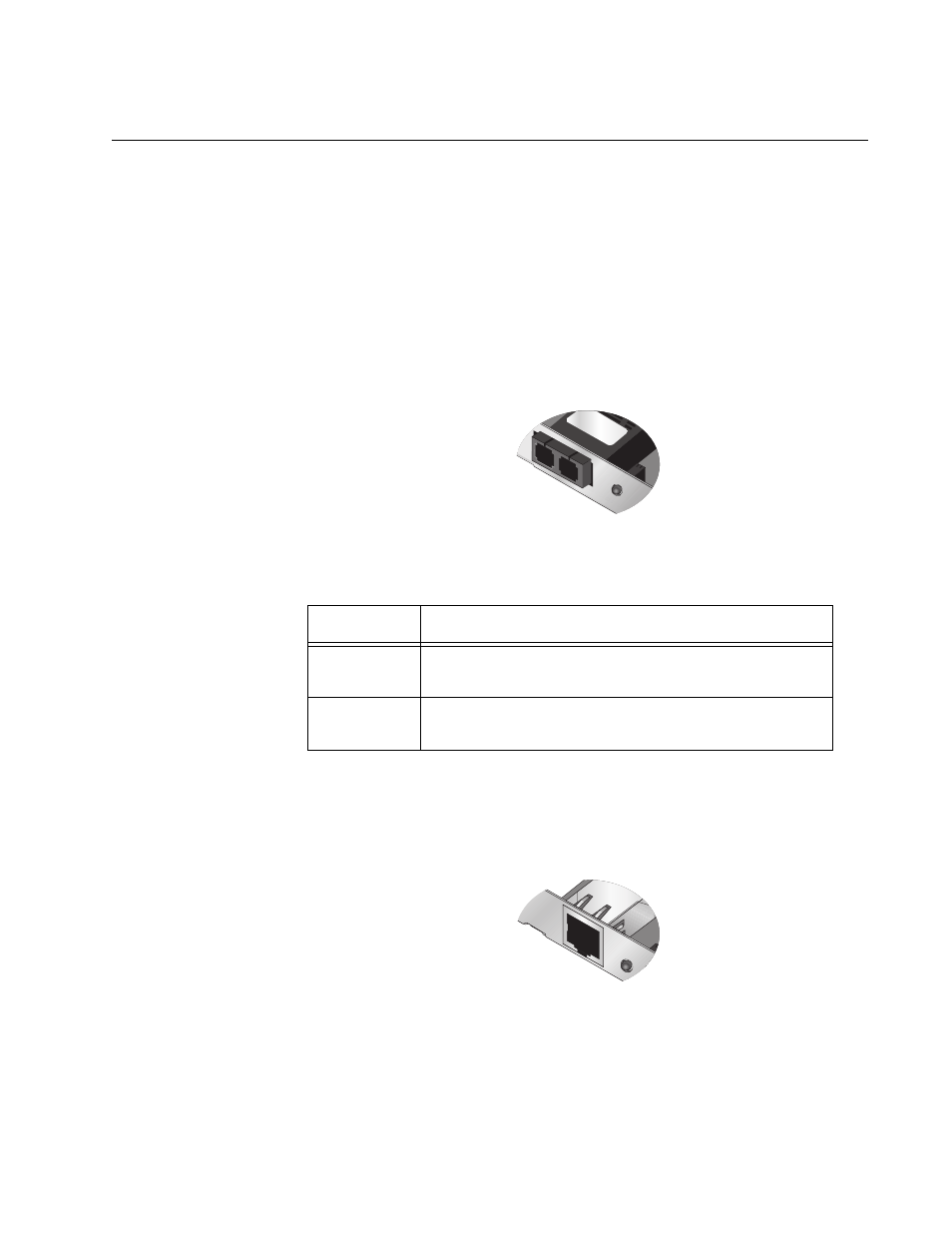
The faceplate on the AT-2712FX/SC adapter provides two fiber optic
connectors for attaching the adapter to a compatible link partner. See
Figure 3 for an illustration of the adapter’s faceplate.
The AT-2712FX/SC adapter has one fiber port and one LED, as shown in
Figure 3 and described in Table 1.
Figure 3. AT-2712FX/SC Faceplate
AT-2912T
Adapter Physical
Description
The faceplate on the AT-2912T adapter provides one twisted-pair
connector for attaching the adapter to a compatible link partner. See
Figure 4 for an illustration of the adapter’s faceplate.
Figure 4. AT-2912T Faceplate
Table 1. Fiber Optic Port 100 LED Status
State
Description
Green
The port is operating at 100 Mbps and has a valid
link.
Flashing
The port is receiving or transmitting network packets
at 100 Mbps.
1484
T
100
TX
RX
100
1595
T
L/A