Leds for the stacking slots, Switch id led, Leds for the stacking slots switch id led – Allied Telesis x510 Series User Manual
Page 38
Chapter 1: Overview
38
LEDs for the
Stacking Slots
SFP+ slots 27 and 28 on the 28-port switches and slots 51 and 52 on the
52-port switches may be used as stacking slots to build a VCStack of up to
four switches. For background information, refer to the x510 Series
Installation Guide for Virtual Chassis Stacking. Table 10 defines the LED
states when the slots contain stacking transceivers.
Switch ID LED
The Switch ID LED, shown in Figure 10 on page 39, displays the ID
number of the switch. A stand-alone switch has the ID number 0. Switches
in a VCStack have the numbers 1 to 4. Chapter 5, “Powering On the
Switch” on page 69 has the procedure for verifying and, if necessary,
changing the ID number of the switch.
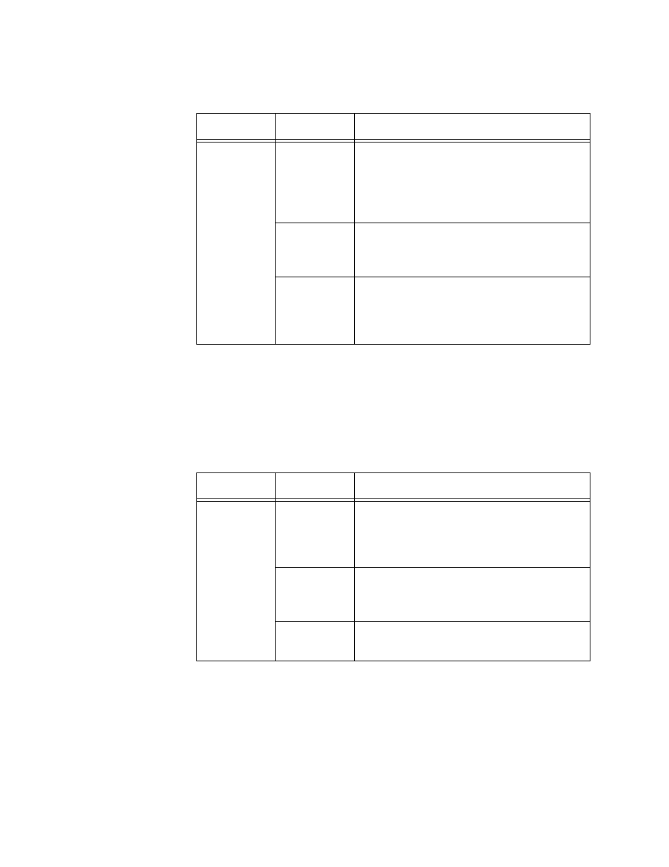
Table 9. SFP+ Slot LEDs
LED
State
Description
Link/Activity
Off
The slot is empty, the SFP or SFP+
transceiver has not established a link to a
network device, or the LEDs are turned
off. To turn on the LEDs, use the eco-
friendly button.
Solid green
The SFP or SFP+ transceiver has
established a link at 1000 Mbps or 10
Gbps to a network device.
Flashing
green
The SFP+ transceiver is receiving or
transmitting packets to a network device
at 10 Gbps. (The LED does not flash for
activity at 1000 Mbps.).
Table 10. Stacking Slot LEDs
LED
State
Description
Link/Activity
Off
The slot is empty, the stacking transceiver
has not established a link to a network
device, or the LEDs are turned off. To turn
on the LEDs, use the eco-friendly button.
Solid green
The stacking transceiver has established
a 10 Gbps link to another switch in the
stack.
Flashing
green
The stacking transceiver is receiving or
transmitting packets.