Aiphone AN-8000 User Manual
Page 7
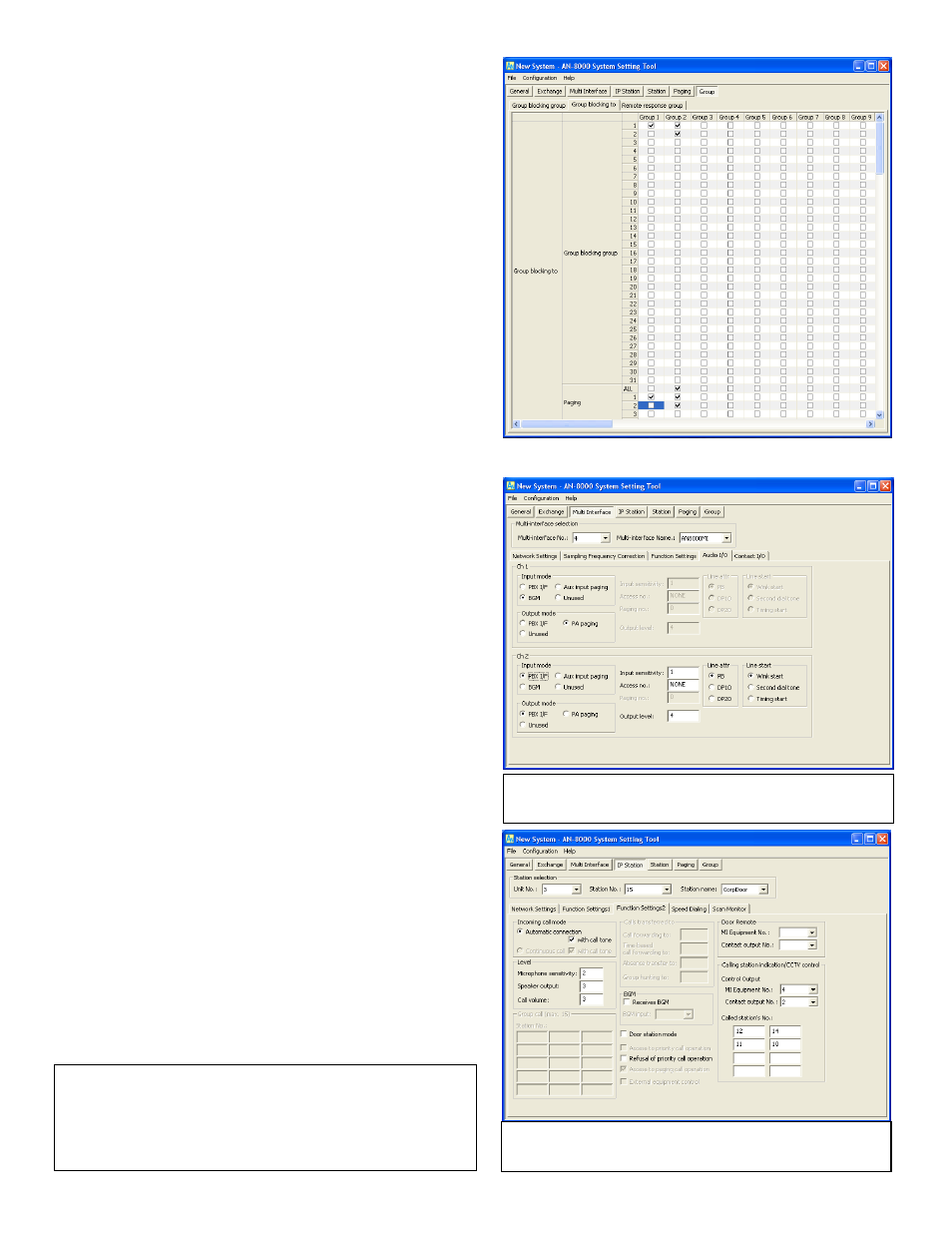
Note: In the example MI configuration channel 1 is for a BGM
source and channel 2 is for a PBX connection.
Note: In the example, MI Equipment No 4 will fire the 2
nd
output
when this station calls a master.
In the “Group blocking to” tab, each column represents
a segment of the system and the rows beneath it determine
access to the other segments. The rule is a checked box
allows an interaction from the Group column to the object
row, a blank box denies that interaction. The reverse is not
necessarily true, so Group 1 may be able to dial Group 2, but
Group 2 would not be able to dial them back unless there is a
check box next to 1 under the Group 2 column.
For Group 1, go down the list and check each box to
enable that Group 1 to call that group. When finished with
Group 1’s permissions, move on to the next column and fill
out Group 2’s permissions in the same way. The All page can
be enabled for a particular group, but each paging zone that
would be part of that All Page must also be enabled.
“Remote response group” is a feature similar to Group
call except the Remote response group members do not ring,
but they may still take an incoming call by using the PTT key.
Step 5.4
Advanced: Integration
Background Music
The Multi Interface section of the program is used to set up
extra paging zones, background music, camera call up, and
what the Contact Inputs and Outputs are used for.
The Audio I/O tab can bring in a music source,
enable auxiliary inputs for paging (such as an automated
message) or background music, or to interface with a PBX.
Once the background music is chosen for one of those 2
inputs, each Exchange or IP Master Function Settings(1) tab
can specify up to 8 different MI channels, which involves an
equipment number (AN-8000MI’s are not named) and the
input (1 or 2). Select the equipment number for the MI that
has the BGM input, then select which of the 2 inputs on the
MI it comes in on. Then go to the Function Settings for each
Station (Function Settings2 if configuring an IP Station) and
check the box next to Receives BGM and tell the station
which BGM channel (1-8) it receives. To operate, a master
can control its own channel by using the sequence Function
+ 1 + X (where X is 1-8 or 0 to turn it off).
Camera Call Up
For Camera call up, select the Station or IP Station
from the Station selection box and switch to the Function
Settings tab (or Function Settings2). In the Calling station
indication/CCTV control box specify which MI Equipment No.
and Contact output No. should provide a make contact when
the station is called. To specify a make contact when this
station calls another, up to 8 can be set by Called station’s
No.
Note: If the contact is being used for door release, you may specify the
contact as such in the Door Remote field of a Station’s Function
Settings tab. This will enable the relay to fire during communication
using the sequence Transfer + Function + 0 for any door. The system
will only fire the relay for the door the operator is currently talking to.