Asante Technologies Voyager II User Manual
Page 88
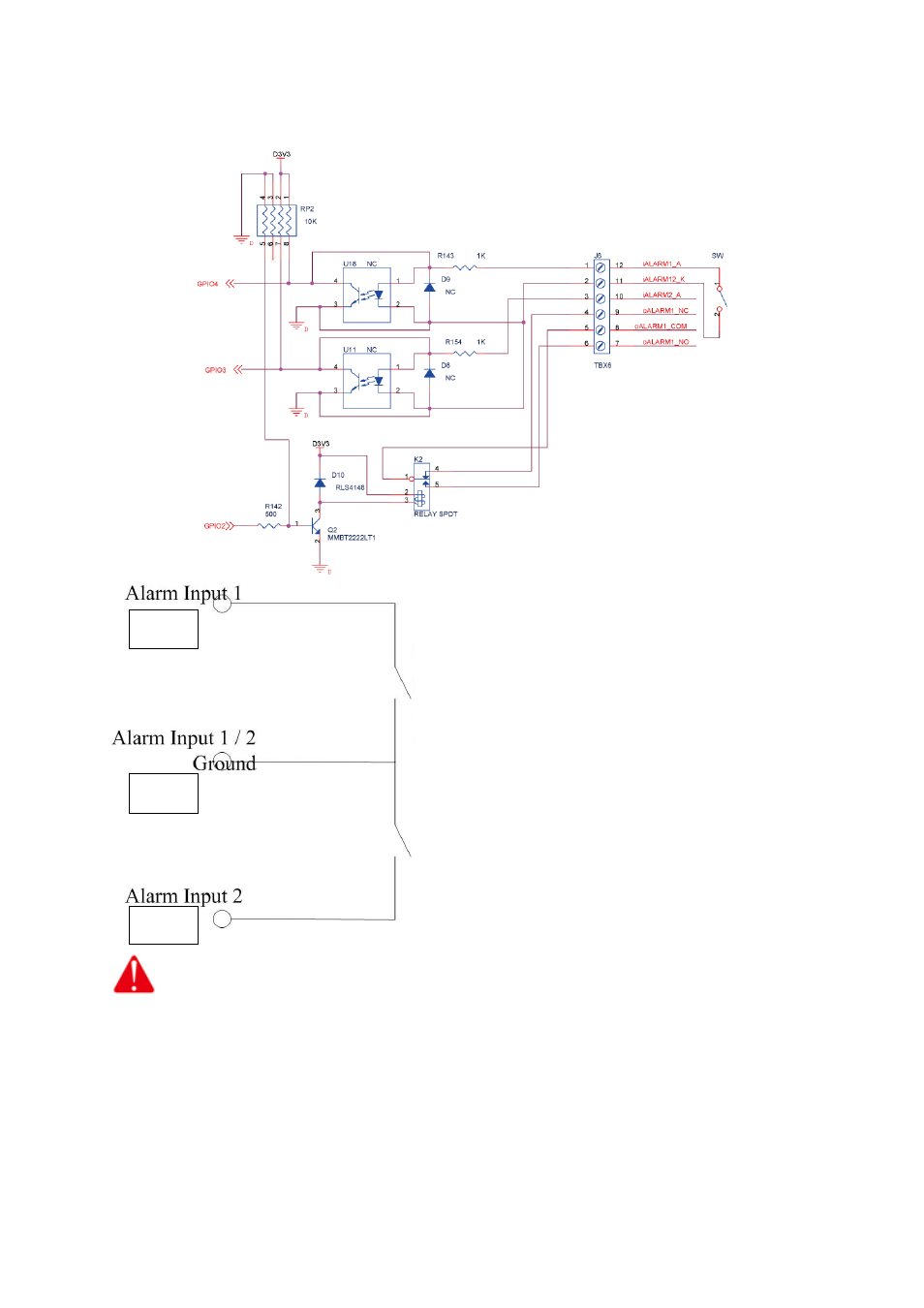
External Alarm I/O Circuit Diagram
Warning! The alarm will be triggered when
alarm pin 2 & 3 are formed as a short circuit.
Please do not connect the electric voltage or
current into alarm input pin because the
electronic current might burn the product.
Warning! The alarm will be triggered
when alarm pin 1 & 2 are formed as a short
circuit. Please do not connect the electric
voltage or current into alarm input pin
because the electronic current might burn the
product.
Pin 1
Pin 2
Pin 3
Warning!
• Where connecting of a low or high current loop to the external alarm input/output of the
product is required, the wiring and connection shall be conducted by a qualified electrician.
Incorrect wiring may bring about damage to the product fatal electric shock.
• Direct connection of the external alarm input/output terminal to high-current equipment is
not allowed and a customized repeat circuit might be required (provided by the customer) for
some cases to isolate the terminal and the high-current equipment. Where the voltage/current
of an external device exceeds the loading capability (DC 50V) of the Alarm I/O, the product
would be damaged seriously.
88