Final installation, Appendix a - remote specifications – Maximum Summit Remote User Manual
Page 9
8
Appendix A - Remote Specifications
Display Range and Resolution
Wind speed
0 to 255 MPH
1 MPH
Wind direction
16 compass points
22.5°
Temperature
-40 to 122 °F
1°F
Power Requirement
24 to 28 VDC @ < 1Amp
Data Link Format
RS-232 levels
2400 baud
8 data bits
1 start bit
1 stop bit
No parity
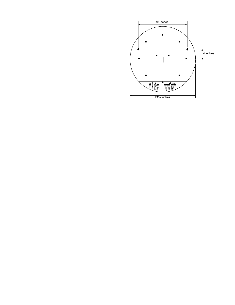
Final installation
The indicator hangs on the wall from the two
hanger holes on the back. The holes will accept #10
or #8 screws and are located on 16 inch centers for
easy mounting (see diagram). Depending on the
wall material you may need to use wall anchors,
molly bolts, etc. Install the indicator mounting
screws now.
Make a hole in the wall behind the Indicator
through which all wires will be fed. CAUTION:
DO NOT MOUNT THE INDICATOR WITH
ANY WIRES UNDER ITS LIP BECAUSE OF
SHORT CIRCUIT HAZARD.
Feed the AC Adapters’ cord from the AC outlet,
through the wall to the Indicator.
Run the data link cable(s) between the master and remote location(s). If you are using line extenders
or short haul modems you should install them now.
At the indicator, connect the cables to the terminal connectors. Plug the terminal connectors into the
indicator. Hang the indicator on the mounting screws.
Plug the AC Adaptor into the 110 VAC outlet. Verify that the POST codes are correct. This com-
pletes the installation of Summit remote.