Section 4. operation of the radiotelemetry network, 1 monitoring and collecting data - pc208w rf notes, 1 basic concepts – Campbell Scientific RF300-Series DRL VHF/UHF Radio Transceivers User Manual
Page 31: 2 using pc208w setup window
4-1
SECTION 4. OPERATION OF THE RADIOTELEMETRY NETWORK
All field stations can be accessed and monitored from the central base site. Regular visits to the field
sites are required to ensure that all sensors are in place, enclosures are dry, solar panel is clean, and
that the tripod and antenna are secure. Frequency of visits to the field sites are variable depending on
environmental conditions and the sensors utilized.
This section of the manual includes a description of the PC208W Datalogger Support Software as it
applies to RF applications, as well as a description of some special RF applications.
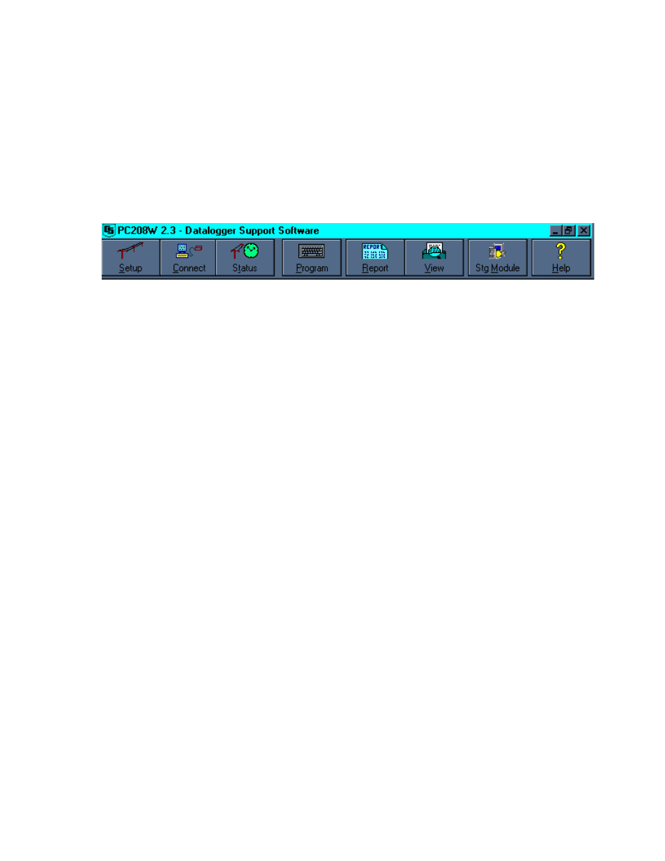
FIGURE 4.1-1 PC208W Main Tool Bar
4.1 MONITORING AND COLLECTING
DATA - PC208W RF NOTES
The PC208W Datalogger Support Software is
the key to communicating with the field stations.
Complete information on the PC208W Software
is included in the PC208W Manual. This
section gives a brief description of software
setup, specific RF application notes, and data
collection methods.
4.1.1 BASIC CONCEPTS
PC208W is designed to use a unique
communication path for each datalogger field
site. Setup communication parameters and a
communication path for each datalogger you
will service. In the Setup Window of PC208W,
see the Device Map. The Device Map shows
each communication path. A typical RF
communication path will start with the RS232
port, usually listed as COM1 or COM2. The
next item in the typical communication path is
the RF Modem, RF95A. After the RF Modem,
each datalogger is connected to the RF
Modem. The name and address (“Dialed using
RF Path”) of each datalogger can be changed.
4.1.2 USING PC208W SETUP WINDOW
This section covers the basic RF
Communications Path. The RF path must be
setup for PC208W to communicate with an RF
field site. See section 2.2.2 for additional
information about the setup window. To create
an RF communication path, open the Setup
Window of PC208W. Next select the COM
port. If you need an RS232 port other than
COM1, use the “Add COM Port” button. Use
the “Add Device…” button to add your RF
modem or Phone modem to the COM port. The
Add Device button opens the “Add New Device”
Dialog box. Once a device is selected the
“Attach Selected Device to” box is opened.
When adding a device you must attach it to a
device in bold lettering. The last device to add
is a datalogger. Using the Add Device button,
add the appropriate datalogger. The
dataloggers are attached to the RF Modem.
Many dataloggers can be attached to one RF
Modem. If a mistake is made, highlight the
mistaken device in the Device Map and use the
Delete button.
There are several fields requiring unique
settings. PC208W Setup window shows
different options based on which device is
selected in the Device Map. Select a device by
left clicking your mouse on the device. Do not
change any settings for the COM port unless
you are doing Callback. Select the RF modem,
the default name is RF1. Using the “RF Modem
Name” box, you can change the name of the
RF modem. The “Baud rate” box can be used
to change the communication rate between the
RF modem and the datalogger. Select 9600
baud for the RF95 and RF95A RF modems.
Older RF modems must remain at 1200 baud.
The datalogger has one setting that must be
changed. Select the “Dialed Using RF Path”
box and enter the address of the RF95A. The
address is the value set with the dip switches
inside the RF95A. See section 3.1.3 for details.