2 rf300 radios, 1 radio description, 2 radio specifications – Campbell Scientific RF300-Series DRL VHF/UHF Radio Transceivers User Manual
Page 24: Rf300
SECTION 3. RADIOTELEMETRY NETWORK COMPONENTS
3-6
Appendix H contains the pin out for the radio to
modem cables.
TABLE 3-4. RF95/A Serial I/O to Datalogger
Connector Description
Pin
Description
1
+5 V: Supply from external source
2
GND: Ground
3
Ring: Ring to datalogger
4
RXD: Transmit from RF95A
5
ME: Modem Enable from datalogger
6
Printer Enable: Not used
7
Unload Enable: Not used
8
Tape Enable: Not used
9
TXD: Received by RF95A
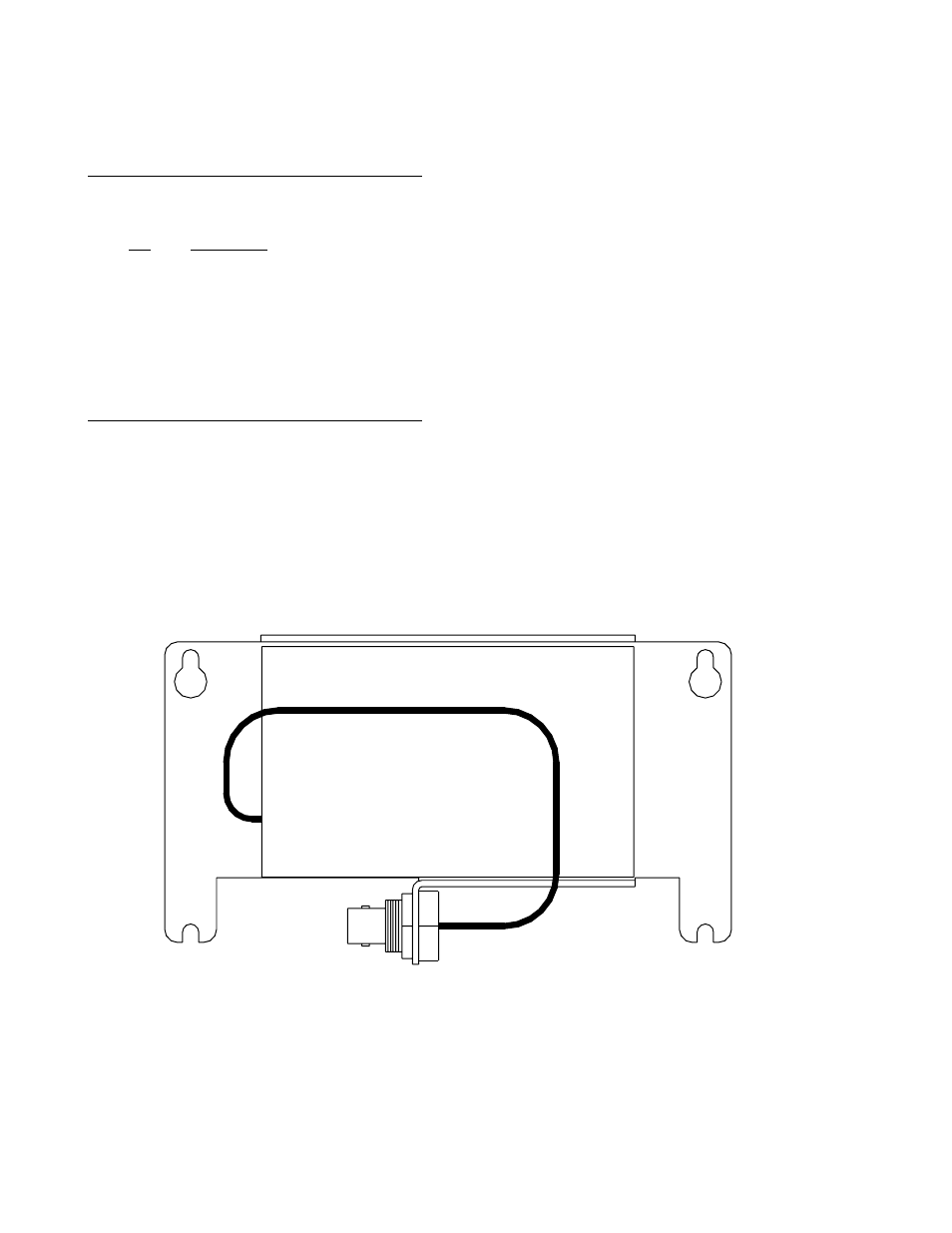
3.2 RF300 RADIOS
3.2.1 RADIO DESCRIPTION
The RF300 is used in Campbell Scientific's RF
applications to transmit and receive data blocks.
The radios are shipped from Campbell Scientific
secured on a mounting bracket designed to
fasten on the top of the RF modem (see Figure
3-3).
The mounting bracket also supports a BNC
Jack connector from the radio. The coax cable
that is required to connect the radio to its
antenna should be connected to the radio at this
BNC connector. See Section 3.3 for more
information on the antenna cable.
The RF300 Radios are connected to the RF
modem by a special radio cable. The first 10-
pin connector on this radio cable has a red and
black wire coming out of the connector. This is
the 10-pin connector (labeled "radio") that
should be connected to the radio. The red and
black power wires should be connected to 12V
and Ground respectfully. The second 10-pin
connector (labeled "RF modem") should be
connected to the RF modem.
3.2.2 RADIO SPECIFICATIONS
The RF300 radios are manufactured by
Johnson Data Telemetry (JDT). Campbell
Scientific modifies the radios to work with the
RF95A Modem. Appendix H contains the radio
specifications.
RF300
FIGURE 3-3. RF300 On Bracket With Connector