3 setting station id, 4 the carrier detect light, 5 data transfer rate – Campbell Scientific RF300-Series DRL VHF/UHF Radio Transceivers User Manual
Page 20
SECTION 3. RADIOTELEMETRY NETWORK COMPONENTS
3-2
TABLE 3-1. A Sample of Station ID Numbers
and the Corresponding Switch Settings
Station
Switch Settings
ID
1234
56789
0
0000
0000X
10
0101
0000X
20
0010
1000X
30
0111
1000X
40
0001
0100X
50
0100
1100X
60
0011
1100X
70
0110
0010X
80
0000
1010X
90
0101
1010X
100
0010
0110X
110
0111
0110X
120
0001
1110X
130
0100
0001X
*
Station ID 255 is reserved for
phone-to-RF base stations.
The RF95A is shipped with the switch set for
the RF95A-ME state and station ID of 1.
Further information on the RF95A compatibility
with older Campbell Scientific equipment can be
found in Appendix F “Equipment Compatibility.”
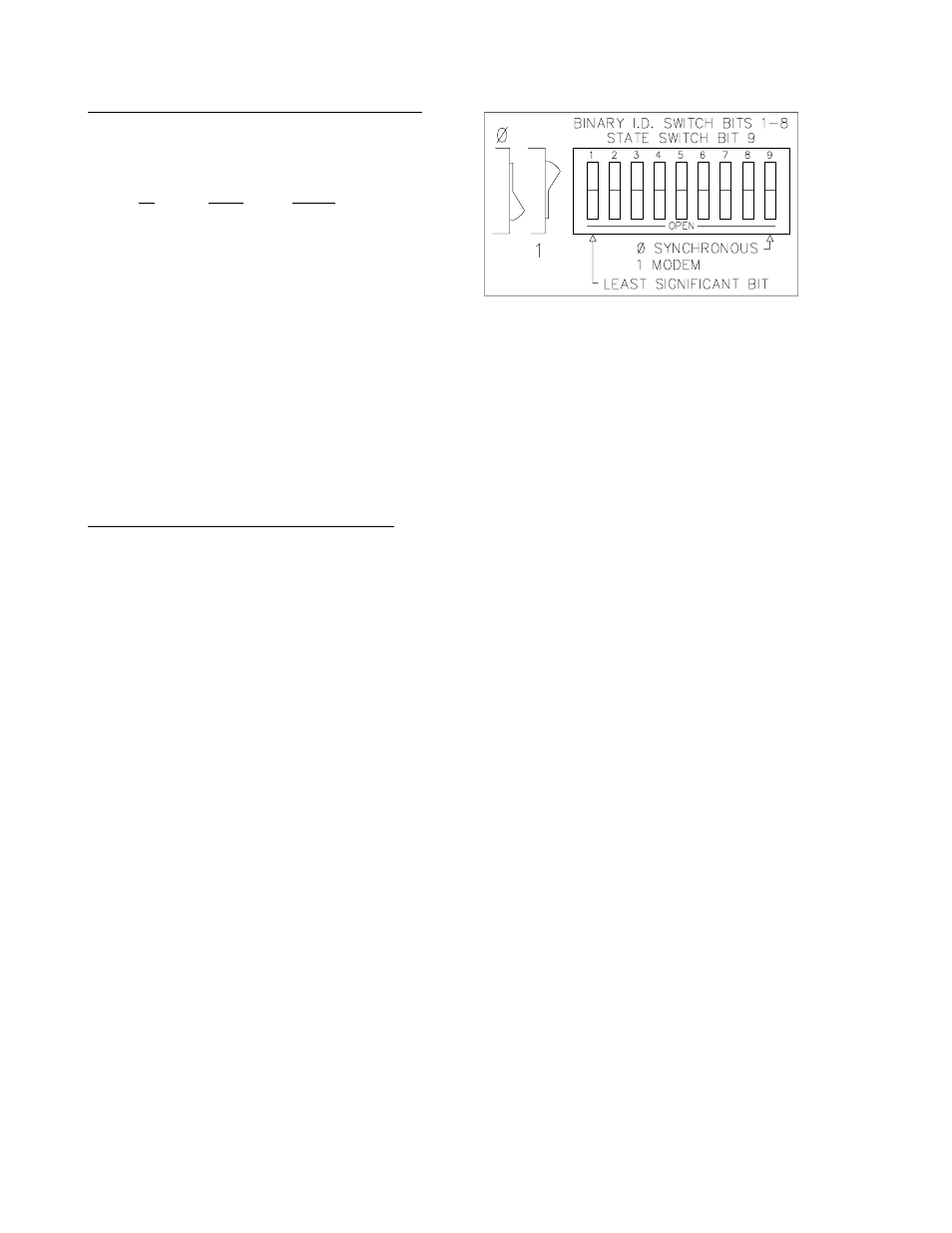
3.1.3 SETTING STATION ID
Each RF95A, including the one in the RF base
station, must have a unique Station ID. The
station ID is similar to a phone number. This
allows one base station to communicate with
any one particular field station.
The Station ID can be any number from 1 to
255. The Station ID is set with the switch inside
the RF95A. The first eight dip switches are
used to set the Station ID. Table 3-1 shows the
switch settings for several Station ID numbers.
Appendix A shows all possible Station ID
numbers. The dip switches can either be open,
represented by 1, or closed, represented by 0;
X in Table 3-1 refers to "don't care." The ninth
dip switch is set according to the desired RF95A
state, see Section 3.1.2 "RF95A States." All
RF95s are shipped with a Station ID of 1 and
are set in the RF95A-ME state. RF95s inside
the RF base station ship with a station ID of 254
and RF95A-ME state.
FIGURE 3-2. Setting the Station ID
3.1.4 THE CARRIER DETECT LIGHT
The Carrier Detect light on the front panel of the
RF95A has several purposes. The primary
function of the light is to indicate when data is
being received or transmitted. The light will stay
on when a network frequency originating from
another RF95A is detected. If a signal is
detected which isn't intended for that station, the
light will shut off after about two-tenths of a
second.
The Carrier Detect light can also be used to
check the RAM (Random Access Memory) and
ROM (Read Only Memory) of the RF95A. With
the radio disconnected and the datalogger in
the LOG (*0) Mode, connect the datalogger to
the RF95A Serial I/O Port with a 9-pin ribbon
cable. The sequence of the light flashing after
connection indicates the RAM and ROM status.
Both the RAM and ROM are good if the light
goes on for one second, off for one second, and
then back on for one second. The RAM is
faulty if the light is on for one half second and
off for one half second, continuously. The ROM
is faulty if the light goes on for one second, off
for one half second, on for one half second, and
then off for one half second, continuously.
3.1.5 DATA TRANSFER RATE
The data transfer rate is the time it takes to get
data from the datalogger to the computer. In
general, data can be transferred at a rate of
about 30 data points/second (60 bytes/second)
without a repeater. If a repeater is used, an
approximate data transfer rate is 22 data
points/second.