Campbell Scientific RF300-Series DRL VHF/UHF Radio Transceivers User Manual
Page 12
SECTION 2. ASSEMBLING THE RADIOTELEMETRY NETWORK
2-2
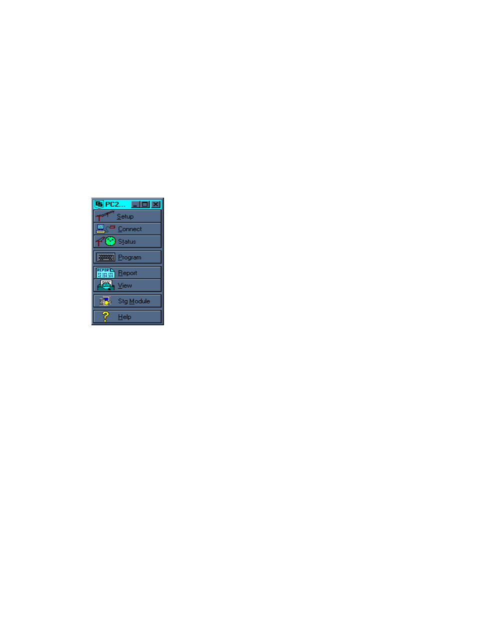
•
REPORT - Generates reports and reduces
data stored on computer.
•
VIEW - Used to view text files.
•
STG MODULE - Used to service storage
modules, SM192 or SM716.
•
HELP - On line help. Also accessed
anywhere by typing F1.
PC208W uses a main tool bar to access each
of the eight windows. The shape of the main
tool bar can be changed using standard
Windows methods. Closing the main tool bar
closes all other PC208W windows.
The SETUP window is used to create a device
map which contains the RF Link information.
This information includes the station ID,
communication path and conditions for calling a
particular field station. Procedures for creating an
RF communications link are explained in section
1 of the PC208W manual.
Basic steps required to setup an RF link include:
1) select appropriate communications port (COM
Port), 2) attach RF modem to COM port, and 3)
attach datalogger to RF modem. The default COM
port settings should not be changed. The RF
modem default settings will work for current
hardware. Use the hardware tab to select 1200
baud for RF systems using the DC95. The default
datalogger settings do not need changing except for
the “Dialed using RF 95 path:”.
The RF Path (Dialed Using RF 95 Path:), found on
the datalogger hardware tab of the setup screen,
designates which field station to call. In the
example shown, the base station will call the field
station with an RF path of 10. If a repeater is
needed to contact Field Station 10, the repeater ID
must also be specified. For example, "RF Path: 5
10F," would call Field Station 10 through a repeater
with a Station ID of 5. The "F" at the end of the RF
Path is optional and is explained later. Click on
Save Edits.