6 external installation, External installation, Supply not shown) – Campbell Scientific ET107 Evapotranspiration Monitoring Station User Manual
Page 63
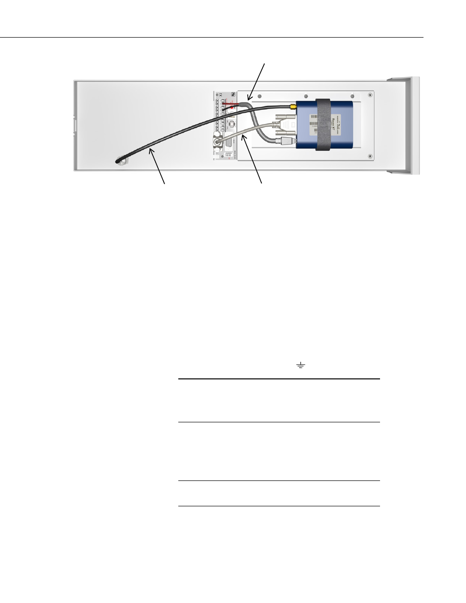
ET107 Weather Station
FIGURE 2-42. RavenXT cellular modem mounted inside the ET107
(power supply not shown).
1. Fasten the mounting bracket to the ET enclosure using the three pre-
threaded screws provided.
2. Thread the smaller SMA connector end of the enclosure antenna cable
underneath the battery cables and screw it to the antenna connector on the
cellular modem. Attach the other end of the cable to the BNC RF
bulkhead connector in the lower right hand corner of the enclosure. Make
sure all connections are tight. See FIGURE 2-42.
3. Use the null modem cable to connect the cellular modem’s serial port to
the ET107’s RS-232 9-pin port. See FIGURE 2-42.
4. Attach the power cable to the cellular modem. Insert the power cable’s red
wire into either the ET107’s SW-12 or 12V terminal, and then insert the
power cable’s black wire into the
terminal. See FIGURE 2-42.
Connection to the SW-12 terminal allows the ET107 to switch
power to the modem during scheduled transmission intervals, thus
conserving power. This connection is recommended for solar-
powered ET stations. Custom programming required.
2.5.5.6 External Installation
The 20679 800 MHz/0 dBd and 1.9 GHz/3 dBd Omnidirectional Cellular
Antenna or the 10530 800 MHz Cellular 9dBd YAGI Antenna should have
been ordered with the kit.
Mounting hardware that comes in the box with the antenna will
not be used.
NOTE
NOTE
Power Cable
(provided with the cellular modem)
Null Modem Cable
12-in. Coaxial Cable
53