4 switch closures on control ports (rain gage) – Campbell Scientific CR510 Basic Datalogger User Manual
Page 99
SECTION 8. PROCESSING AND PROGRAM CONTROL EXAMPLES
8-3
02:
If time is (P92)
1:
0
Minutes (Seconds --) into a
2:
15
Interval (same units as above)
3:
10
Set Output Flag High
03:
Set Active Storage Area (P80)
1:
3
Input Storage Area
2:
2
Array ID or Loc [ 15min_tot ]
04:
Totalize (P72)
1:
1
Reps
2:
1
Loc [ Precip_mm ]
05:
IF (X<=>F) (P89)
1:
2
X Loc [ 15min_tot ]
2:
2
<>
3:
0
F
4:
30
Then Do
06:
Set Active Storage Area (P80)
1:
1
Final Storage Area 1
2:
25
Array ID or Loc
[ _________ ]
07:
Real Time (P77)
1: 0110
Day,Hour/Minute
08:
Sample (P70)
1:
1
Reps
2:
2
Loc [ 15min_tot ]
09:
End (P95)
INPUT LOCATIONS
1 Precip_mm
2 15min_tot
8.3 SUB 1 MINUTE OUTPUT INTERVAL
SYNCHED TO REAL TIME
Output can be synchronized to seconds by
pressing “-” or “C” while entering the first
parameter in Instruction 92. If a counter,
incremented within the program, was used to
determine when to set the Output Flag, output
would depend on the number of times the table
was executed. The actual time of output would
depend on when the program was actually
compiled and started running. If the table
overran its execution interval (Section 1.1.1),
the output interval would not be the count
multiplied by the execution interval, but some
longer interval.
In this example a temperature (107
Temperature Probe) is measured every 0.5
seconds and the average output every 30
seconds.
PROGRAM
*
Table 1 Program
01:
0.5
Execution Interval (seconds)
01:
Temp (107) (P11)
1:
1
Reps
2:
1
SE Channel
3:
1
Excite all reps w/E1
4:
1
Loc [ Temp ]
5:
1.0
Mult
6:
0.0
Offset
02:
If time is (P92)
1:
0--
Minutes (Seconds --) into a
2: 30
Interval (same units as above)
3: 10
Set Output Flag High
03:
Average (P71)
1:
1
Reps
2:
2
Loc [ TC_Temp ]
INPUT LOCATIONS
1 Ref_Temp
2 TC_Temp
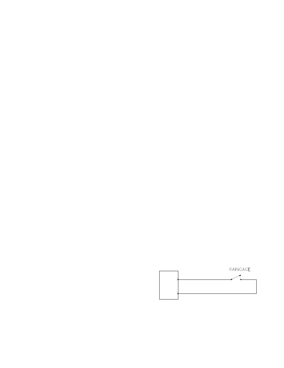
8.4 SWITCH CLOSURES ON CONTROL
PORTS (RAIN GAGE)
Control port 2 can be used to measure switch
closures up to 40 Hz. Instruction 3, pulse, is
used to measure two rain gages on pulse input
1, and a rain gage with control port 2. This is
done as a comparison. In a real application the
pulse channel would be used for wind speed
and a control port for a rain gage. The rain
gage is connected as diagrammed below.
+5
C2/P3
CR510
FIGURE 8.4-1. Connections for Rain Gage