Campbell Scientific CR510 Basic Datalogger User Manual
Page 83
SECTION 7. MEASUREMENT PROGRAMMING EXAMPLES
7-5
Next solve for V
x
:
V
x
= I(R
1
+R
s
+R
f
) = 2.21 V
If the actual resistances were the nominal
values, the CR510 would not over range with V
x
= 2.2 V. To allow for the tolerances in the actual
resistances, it is decided to set V
x
equal to 2.1
volts (e.g., if the 10 kohms resistor is 5% low,
then R
s
/(R
1
+R
s
+R
f
)=115.54/9715.54, and V
x
must be 2.102 V to keep V
s
less than 25 mV).
The result of Instruction 9 when the first
differential measurement (V
1
) is not made on
the 2.5 V range is equivalent to R
s
/R
f
.
Instruction 16 computes the temperature (
°
C)
for a DIN 43760 standard PRT from the ratio of
the PRT resistance at the temperature being
measured to its resistance at 0
°
C (R
s
/R
0
).
Thus, a multiplier of R
f
/R
0
is used in Instruction
9 to obtain the desired intermediate, R
s
/R
0
(=R
s
/R
f
x R
f
/R
o
). If R
s
and R
0
were each
exactly 100 ohms, the multiplier would be 1.
However, neither resistance is likely to be exact.
The correct multiplier is found by connecting the
PRT to the CR510 and entering Instruction 9
with a multiplier of 1. The PRT is then placed in
an ice bath (@ 0
°
C; R
s
=R
0
), and the result of
the bridge measurement is read using the
∗
6
Mode. The reading is R
s
/R
f
, which is equal to
R
o
/R
f
since R
s
=R
o
. The correct value of the
multiplier, R
f
/R
0
, is the reciprocal of this
reading. The initial reading assumed for this
example was 0.9890. The correct multiplier is:
R
f
/R
0
= 1/0.9890 = 1.0111.
The fixed 100 ohm resistor must be thermally
stable. Its precision is not important because
the exact resistance is incorporated, along with
that of the PRT, into the calibrated multiplier.
The 10 ppm/
°
C temperature coefficient of the
fixed resistor will limit the error due to its change
in resistance with temperature to less than
0.15
°
C over the specified temperature range.
Because the measurement is ratiometric
(R
s
/R
f
), the properties of the 10 kohm resistor
do not affect the result.
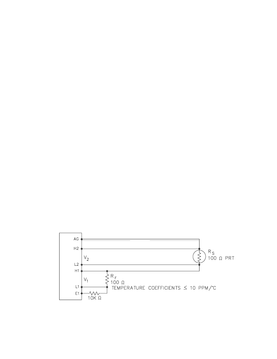
A terminal input module (Model 4WPB100) can
be used to complete the circuit shown in Figure
7.8-1.
PROGRAM
01:
Full Bridge w/mv Excit (P9)
1:
1
Reps
2:
23
±
25 mV 60 Hz Rejection
Ex Range
3:
23
±
25 mV 60 Hz Rejection
Br Range
4:
1
DIFF Channel
5:
1
Excite all reps w/Exchan 1
6: 2100
mV Excitation
7:
1
Loc [ Rs_Ro ]
8:
1.0111
Mult
9:
0
Offset
02:
Temperature RTD (P16)
1:
1
Reps
2:
1
R/Ro Loc [ Rs_Ro ]
3:
2
Loc [ Temp_C ]
4:
1
Mult
5:
0
Offset
CR510
FIGURE 7.6-1. Wiring Diagram for PRT in 4 Wire Half Bridge